between 1 - 1.2m long. The hose should not be subjected to abrasion, kinking or permanent deformation and
should be able to be inspected along its entire length. Unions compatible with the hose fittings must be used
and connections tested for gas leaks. The flexible tube shall be fitted in such a way that it cannot come into
contact with a moveable part of the housing unit (e.g. a drawer)and does not pass through any space
susceptible of becoming congested. The fixed consumer piping outlet should be at approximately the same
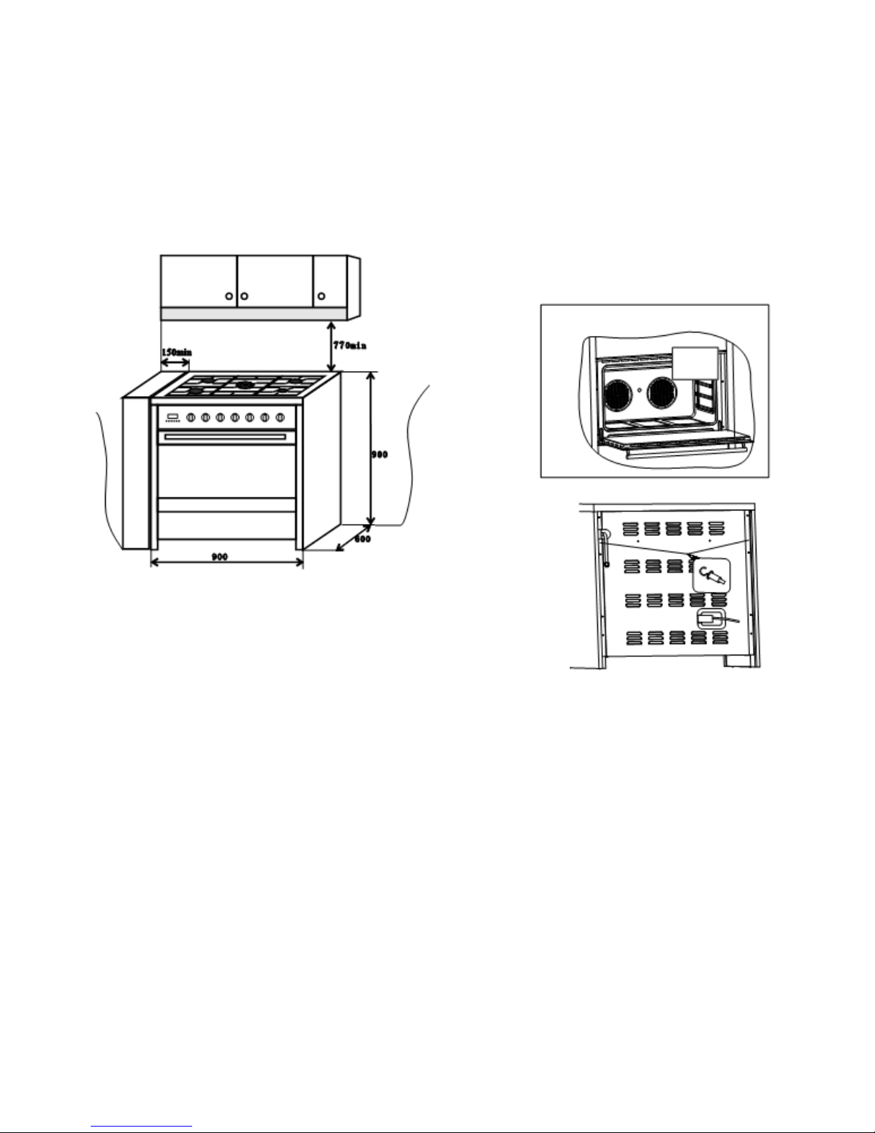
height as the cooker connection point, pointing downwards and approximately 150mm to the side of the
cooker. The hose should be clear of the floor when the cooker is in the installed position. Fix one end of the
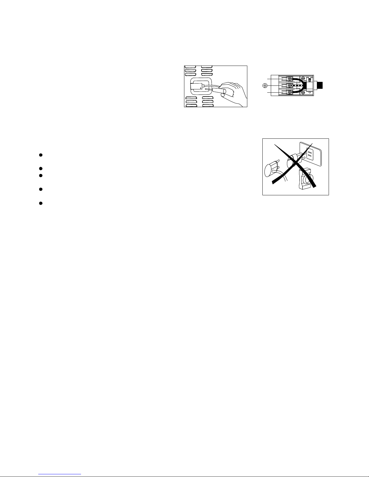
chain on the screw next to the gas inlet connection and the other end should be anchored to the floor/wall so
that the chain prevents strain on the hose connections when he cooker is pulled forward.
The appliance is factory set for Natural gas. The test point pressure should be adjusted to 20mbar with the
Triple ring burner operating at maximum.
The appliance is set up to operate with the gas specified on the gas type label placed on the back of the
appliance.
To perform these operations the qualified installer will follow the indications given in the "Adaptation to the
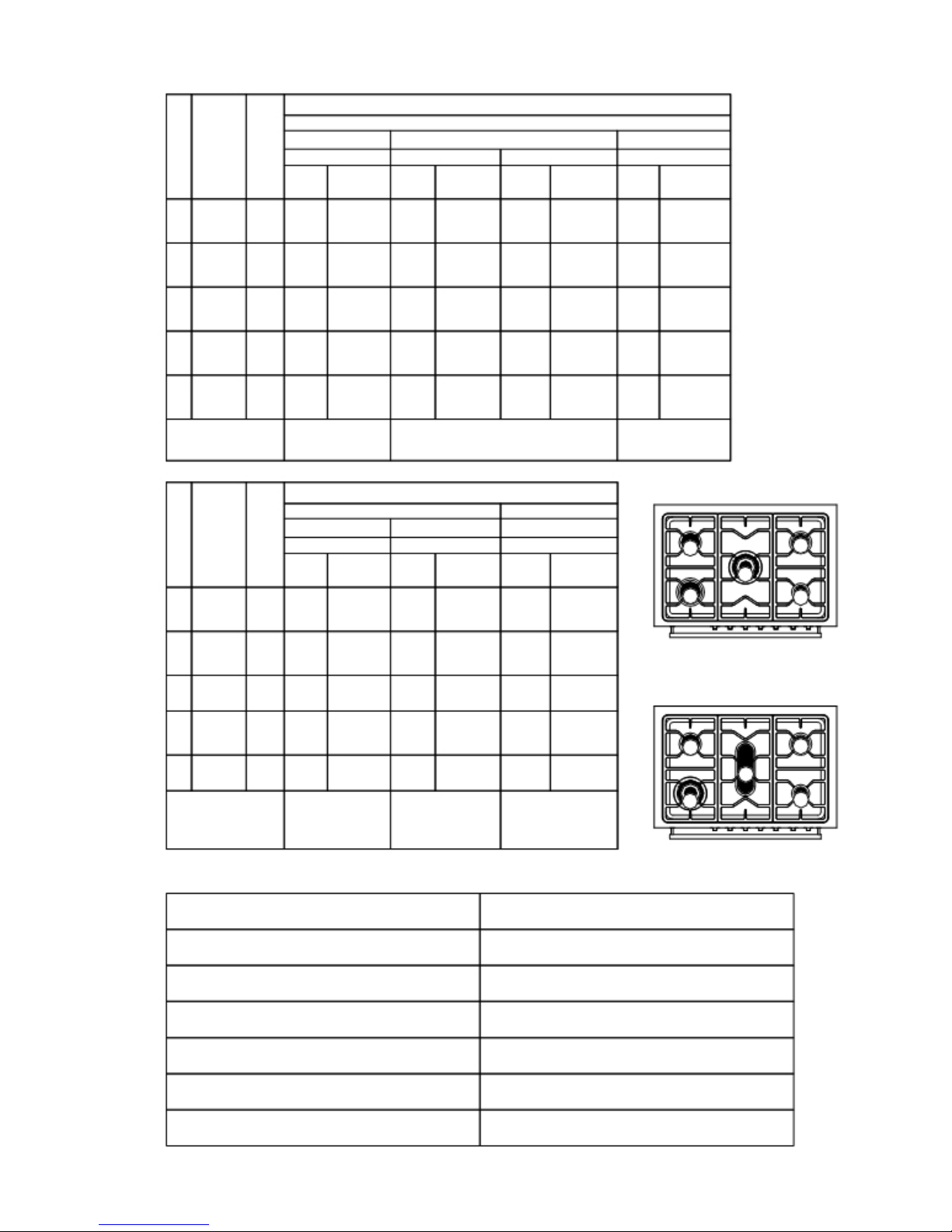
various types of gas" section. For safer operation make sure that the supply pressure respects the values given in the
"Table of burner and injector characteristics".
If installing for use with LPG gas, ensure a gas regulator suitable for a supply pressure of 29mbar is part of the
gas tank supply and the test point pressure is adjusted to 29mbar
If installing for use with TG gas, ensure a gas regulator suitable for a supply pressure of 8mbar is part of the
gas tank supply and the test point pressure is adjusted to 8mbar
Once the appliance has been installed, make sure that the gas pipe is neither squashed or damaged by moving
parts.
Before Leaving - Check all connections for gas leaks with soap and water. DO NOT use a naked flame for
detecting leaks. Igniteall burners both individually andseparately to ensure correct operation of gas valves, burners
and ignition. Turn gas taps to low flame position and observe stability of the flame for eachburner individually and
separately. When satisfied with the operation of the cooker, please instruct the user on the correct method of
operation. In case the appliance fails to operate correctly after all checks have been carried out, refer to the authorised
service provider in your area.
Adaptation to different types of gas
WhenconvertingfromUniversal LPG toNaturalGas ensurethat theLPG testpoint is removed and replacedwith the
CE Approved NG Regulator supplied in this kit. The test point pressure must be adjusted to
20mbar with the largest burner operating on maximum flame.
When converting from Natural Gas to Universal LPG ensure that the NG regulator is removed and replaced
with the Test Point Assembly supplied in this kit. An CE Approved gas regulator suitable for a supply pressure
of 29mbar should be part of the gas tank supply and the test point pressure must be adjusted to 29mbar.
To adapt the appliance to a gas different from that
for which it was set up (see gas type label inside
the warming compartment door) proceed as follows:
gas available (see burner and injector characteristics Table)
When converting from Natural Gas to LPG ensure that the NG regulator is removed and replaced with the Test
Point Assembly. A gas regulator suitable for a supply pressure of should be part of the gas tank supply and the
test point pressure should be adjusted to the pressure according to the data plate.
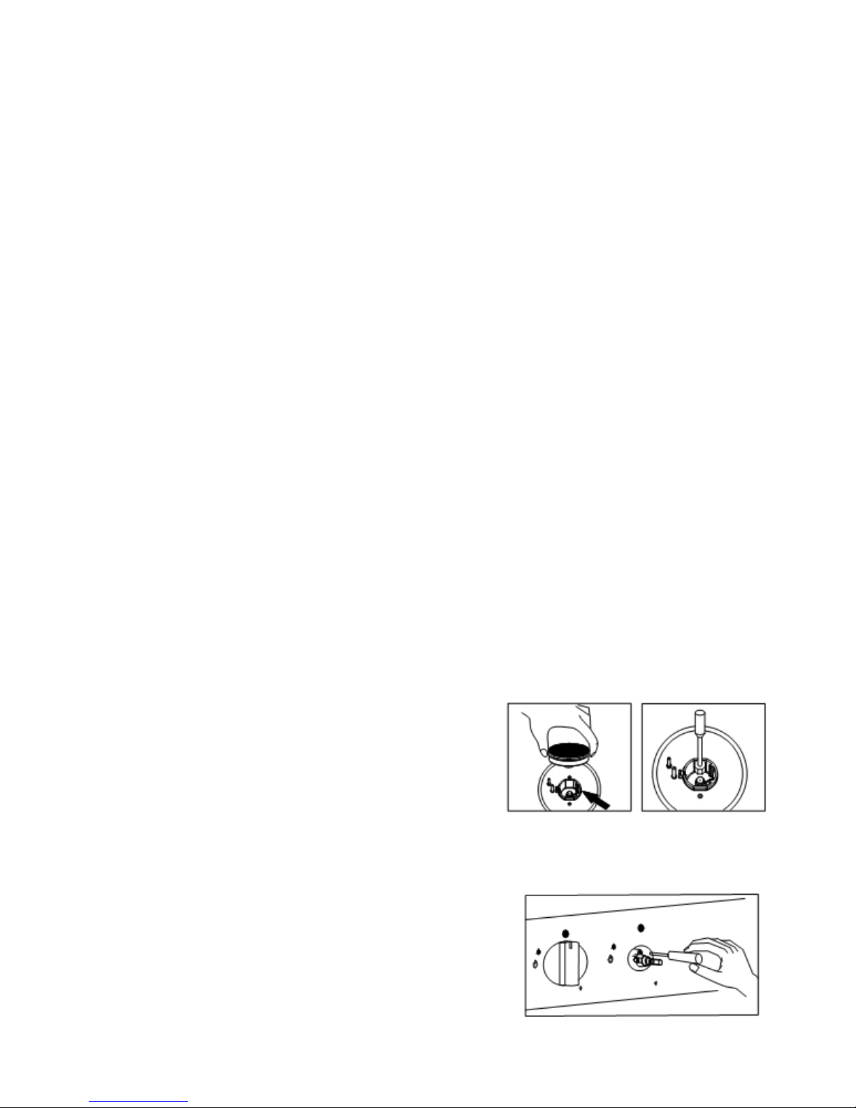
Setting the minimum flame
The flame on the small output is regulated by the factory.
When theinjectorshavebeen replacedor therearespecial mains
pressure conditions, it may be necessary to regulate the
minimum flame again. The operations necessary to set the
minimum flame are as following:
7