Veratron A2C59501987 User manual

TIMELESS INSTRUMENTS
VIEWLINE
110MM
GPS SPEEDOMETERS
USER MANUAL
rev. AA
EN
DE
IT
FR
ES
PT

CONTENT
2
CONTENT
INTRODUCTION ........................................................................................3
Part Numbers ............................................................................................................... 3
TECHNICAL DATA .....................................................................................3
SAFETY INFORMATION ......................................................................... 4
Safety During Installation ....................................................................................... 4
Safety After Installation ........................................................................................... 5
Electrical Connection .............................................................................................. 5
MECHANICAL INSTALLATION ............................................................ 6
Before t e Assembly ................................................................................................ 6
Installation wit Spinlock ........................................................................................ 7
Flus Mounting ........................................................................................................... 8
Installation wit Brackets ....................................................................................... 9
ELECTRICAL INSTALLATION ............................................................. 10
Pinout ............................................................................................................................ 10
LCD OPERATION ..................................................................................... 11
Basics .............................................................................................................................. 11
Alarm and Clock ........................................................................................................ 11
Brig tness .................................................................................................................... 12
In Operation ................................................................................................................ 12
ACCESSORIES.......................................................................................... 14

INTRODUCTION & TECHNICAL DATA
3
INTRODUCTION
T e ViewLine GPS speedometer wit embedded GPS receiver is a
plug-and-play device wit NMEA 2000 capability. Wit anti-fog
plastic double lens, it offers maximum precision and stylis design
wit c oice of nine various bezels. T e design concept offers a ig
level of installation flexibility for panel- and flus mounting.
D splayed data: GPS signal quality, COG, UTC time, Trip distance,
Trip time
PART NUMBERS
T ere are t ree different versions of t is gauge, eac wit a different
measurement range.
Eac device can be configured to work wit metric, imperial and
nautical measurement units.
Part Number Range
A2C59501987 12
A2C59501782 35
A2C59501781 70
TECHNICAL DATA
Supply Voltage 12 V (8-16V operating range, wit reverse polarity protection)
Current consumpt on < 150 mA wit warning LED (< 500 µA quiescent current)
D splay 37 x 11 mm, LCD
Protect on class IP 67 front side, IP 52 rear side acc. IEC60529:2001
Lens PMMA double lens
Hous ng Polycarbonate (PC), flame retardant acc. UL94-V0
Bezels PC (black, w ite); ABS (c rome)
Po nter
Illumination: Red LED
240° deflection angle
Illum nat on Dial: amber, Pointer: red, Scale unit indication: green, Warning LED: red
Operat ng
temperature
-
20°C to +85°C
wit c rome bezel -40°C to +70°C
Storage temperature
-
40°C to +8
5
°C
wit c rome bezel -40°C to +70°C
Connector Tyco / Hirsc mann MQS connector 8 pin
Mount ng
Diameter: 110mm ( ousing diameter)
Top mount: Clamp ring or studs and bracket
Flus mount: Fixing Bracket (A2C53244511)
Installat on depth 50 mm (wit out connector)
Cert f cat ons CE

SAFETY INFORMATION
4
SAFETY INFORMATION
WARNING
•No smoking! No open fire or eat sources!
•T e product was developed, manufactured
and inspected according to t e basic safety
requirements of EC Guidelines and state-of-
t e-art tec nology.
•T e instrument is designed for use in grounded
ve icles and mac ines as well as in pleasure
boats, including non-classified commercial
s ipping.
•Use our product only as intended. Use of t e
product for reasons ot er t an its intended use
may lead to personal injury, property damage
or environmental damage. Before installation,
c eck t e ve icle documentation for ve icle
type and any possible special features!
•Use t e assembly plan to learn t e location of
t e fuel/ ydraulic/compressed air and
electrical lines!
•Note possible modifications to t e ve icle,
w ic must be considered during installation!
•To prevent personal injury, property damage or
environmental damage, basic knowledge of
motor ve icle/s ipbuilding electronics and
mec anics is required.
•Make sure t at t e engine cannot start
unintentionally during installation!
•Modifications or manipulations to Veratron
products can affect safety. Consequently, you
may not modify or manipulate t e product!
•W en removing/installing seats, covers, etc.,
ensure t at lines are not damaged, and plug-in
connections are not loosened!
•Note all data from ot er installed instruments
wit volatile electronic memories.
SAFETY DURING INSTALLATION
•During installation, ensure t at t e product’s
components do not affect or limit ve icle
functions. Avoid damaging t ese components!
•Only install undamaged parts in a ve icle!
•During installation, ensure t at t e product
does not impair t e field of vision and t at it
cannot impact t e driver’s or passenger’s ead!
•A specialized tec nician s ould install t e
product. If you install t e product yourself,
wear appropriate work clot ing. Do not wear
loose clot ing, as it may get caug t in moving
parts. Protect long air wit a air net.
•W en working on t e on-board electronics, do
not wear metallic or conductive jewelry suc as
necklaces, bracelets, rings, etc.
•If work on a running engine is required, exercise
extreme caution. Wear only appropriate work
clot ing as you are at risk of personal injury,
resulting from being crus ed or burned.
•Before beginning, disconnect t e negative
terminal on t e battery, ot erwise you risk a
s ort circuit. If t e ve icle is supplied by
auxiliary batteries, you must also disconnect
t e negative terminals on t ese batteries!
S ort circuits can cause fires, battery
explosions and damages to ot er electronic
systems. Please note t at w en you disconnect
t e battery, all volatile electronic memories
lose t eir input values and must be
reprogrammed.
•If working on gasoline boat motors, let t e
motor compartment fan run before beginning
work.
•Pay attention to ow lines and cable arnesses
are laid so t at you do not drill or saw t roug
t em!
•Do not install t e product in t e mec anical
and electrical airbag area!
•Do not drill oles or ports in load-bearing or
stabilizing stays or tie bars!
•W en working underneat t e ve icle, secure
it according to t e specifications from t e
ve icle manufacturer.
•Note t e necessary clearance be ind t e drill
ole or port at t e installation location.
Required mounting dept : 65 mm.
•Drill small ports; enlarge and complete t em, if
necessary, using taper milling tools, saber saws,

SAFETY INFORMATION
5
key ole saws or files. Deburr edges. Follow t e
safety instructions of t e tool manufacturer.
•Use only insulated tools, if work is necessary on
live parts.
•Use only t e multimeter or diode test lamps
provided, to measure voltages and currents in
t e ve icle/mac ine or boat. Use of
conventional test lamps can cause damage to
control units or ot er electronic systems.
•T e electrical indicator outputs and cables
connected to t em must be protected from
direct contact and damage. T e cables in use
must ave enoug insulation and electric
strengt and t e contact points must be safe
from touc .
•Use appropriate measures to also protect t e
electrically conductive parts on t e connected
consumer from direct contact. Laying metallic,
uninsulated cables and contacts is pro ibited.
SAFETY AFTER INSTALLATION
•Connect t e ground cable tig tly to t e
negative terminal of t e battery.
•Reenter/reprogram t e volatile electronic
memory values.
•C eck all functions.
•Use only clean water to clean t e components.
Note t e Ingress Protection (IP) ratings (IEC
60529).
ELECTRICAL CONNECTION
•Note cable cross-sectional area!
•Reducing t e cable cross-sectional area leads
to ig er current density, w ic can cause t e
cable cross-sectional area in question to eat
up!
•W en installing electrical cables, use t e
provided cable ducts and arnesses; owever,
do not run cables parallel to ignition cables or
to cables t at lead to large electricity
consumers.
•Fasten cables wit cable ties or ad esive tape.
Do not run cables over moving parts. Do not
attac cables to t e steering column!
•Ensure t at cables are not subject to tensile,
compressive or s earing forces.
•If cables are run t roug drill oles, protect
t em using rubber sleeves or t e like.
•Use only one cable stripper to strip t e cable.
Adjust t e stripper so t at stranded wires are
not damaged or separated.
•Use only a soft soldering process or
commercially available crimp connector to
solder new cable connections!
•Make crimp connections wit cable crimping
pliers only. Follow t e safety instructions of t e
tool manufacturer.
•Insulate exposed stranded wires to prevent
s ort circuits.
•Caution: Risk of s ort circuit if junctions are
faulty or cables are damaged.
•S ort circuits in t e ve icle network can cause
fires, battery explosions and damages to ot er
electronic systems. Consequently, all power
supply cable connections must be provided
wit weldable connectors and be sufficiently
insulated.
•Ensure ground connections are sound.
•Faulty connections can cause s ort circuits.
Only connect cables according to t e electrical
wiring diagram.
•If operating t e instrument on power supply
units, note t at t e power supply unit must be
stabilized and it must comply wit t e following
standard: DIN EN 61000, Parts 6-1 to 6-4.

MECHANICAL INSTALLATION
6
MECHANICAL INSTALLATION
WARNING
Before beginning, disconnect t e negative terminal on t e battery, ot erwise you risk a s ort circuit.
If t e ve icle is supplied by auxiliary batteries, you must also disconnect t e negative terminals on t ese
batteries! S ort circuits can cause fires, battery explosions and damages to ot er electronic systems.
Please note t at w en you disconnect t e battery, all volatile electronic memories lose t eir input values
and must be reprogrammed.
BEFORE THE ASSEMBLY
1.
Before beginning, turn off t e ignition and
remove t e ignition key. If necessary, remove
t e main circuit switc .
2. Disconnect t e negative terminal on t e
battery. Make sure t e battery cannot
unintentionally restart.
3. Place t e device at least 300 mm away from any
magnetic compass.

MECHANICAL INSTALLATION
7
INSTALLATION WITH SPINLOCK
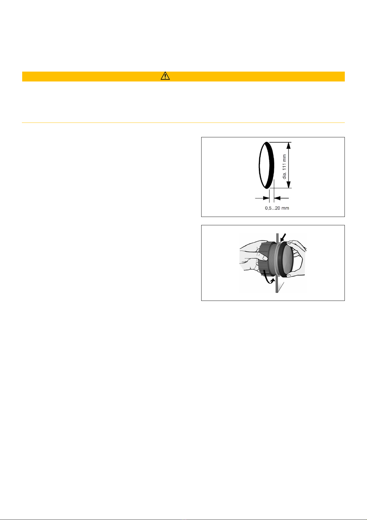
Conventional assembly. (Instrument is put into t e drill ole from t e front).
T e panel t ickness may be wit in a range of 0.5 to 20 mm.
T e drill ole must ave a diameter of 111 mm.
WARNING
•Do not drill oles or ports in load-bearing or stabilizing stays or tie bars!
•Note t e necessary clearance be ind t e drill ole or port at t e installation location. Required
mounting dept : 65 mm.
•Drill small ports; enlarge and complete t em, if necessary, using taper milling tools, saber saws, key ole
saws or files. Deburr edges. Follow t e safety instructions of t e tool manufacturer.
1. Create a circular ole in t e panel considering t e
device dimensions.
2. Remove t e spinlock and insert t e device from
t e front.
3. Align t e instrument and and-tig ten t e
fastening nut. Ensure t at t e nut is not tig tened
wit a torque greater t an 4 Nm.
Make sure t e seal lays flat between t e panel and
t e front ring.

MECHANICAL INSTALLATION
8
FLUSH MOUNTING
T e recommended panel t ickness is 1.5 to 3 mm.
T e drill ole must ave a diameter of 105.4 mm.
Ensure t at t e installation location is level and as no s arp edges.
WARNING
•Do not drill oles or ports in load-bearing or stabilizing stays or tie bars!
•Note t e necessary clearance be ind t e drill ole or port at t e installation location. Required
mounting dept : 65 mm.
•Drill small ports; enlarge and complete t em, if necessary, using taper milling tools, saber saws,
key ole saws or files. Deburr edges. Follow t e safety instructions of t e tool manufacturer.
1. Gently remove t e bezel using a screwdriver.
Note: t e bezel cannot be used after removal
since it mig t be damaged.
2. Create a circular ole in t e panel considering t e
device dimensions.
3. Place t e flus mount seal A2C53215641 (not
included) on t e instrument glass.
4. Put t e instrument into t e drill ole from t e
back.
5. Adjust t e instrument so t at t e gauge is level
and fasten it to t e stud bolts on t e rear side of
t e panel, using t e flus mount fixing bracket
A2C59510864 (not included).

MECHANICAL INSTALLATION
9
INSTALLATION WITH BRACKETS
Conventional assembly. (Instrument is put into t e drill ole from t e front).
T e panel widt may be wit in a range of 0.5 to 20 mm.
T e drill ole must ave a diameter of 111 mm.
WARNING
•Do not drill oles or ports in load-bearing or stabilizing stays or tie bars!
•Note t e necessary clearance be ind t e drill ole or port at t e installation location. Required
mounting dept : 65 mm.
•Drill small ports; enlarge and complete t em, if necessary, using taper milling tools, saber saws,
key ole saws or files. Deburr edges. Follow t e safety instructions of t e tool manufacturer.
1. Create a circular ole in t e panel considering t e
device dimensions.
2. Remove t e spinlock and insert t e device from
t e front.
3. Screw t e stud bolts into t e provided drill oles
in t e enclosure.
Max. stud bolt torque is 1.5 Nm.
4. Place t e bracket on t e stud bolt and and-
tig ten t e knurled nut.
Make sure t e seal lays flat between t e panel
and t e front ring.

ELECTRICAL INSTALLATION
10
ELECTRICAL INSTALLATION
WARNING
•Refer to t e safety rules described in t e electrical connections section of t e safety information
c apter of t is document!
Depending on t e configuration, insert t e cable into t e 8-pin contact enclosure according to t e
following pin assignment.
T e contacts must audibly lock into place.
Now insert t e plug into t e gauge.
Note t e inverse polarity protection nose in t e process.
PINOUT
P n No.
W re color Descr pt on
1 Red KL. 30 – Battery Power 12 / 24 V
2 Black KL. 31 – Ground
3 Green / Red Mode Button (active low)
4 Yellow / Red KL. 15 – Ignition plus
5 Blue / W ite Unit configuration pin
6 W ite / Red KL. 58 – Illumination
7 - NMEA 2000 – CAN Hig
8 - NMEA 2000 – CAN Low
15:
terminal 15
-
Ignition plus
30: terminal 30 - Steady state plus 12V
31: terminal 31 – Ground
58: terminal 58 – Illumination
F1: Fuse (5A quick-response)
C1: 8-Pin MQS Connector
C2: NMEA 2000® Micro-C M12 male
C3: bullet connectors (4mm)
T e measurement unit is defined by t e
connection made on t e config pin.
Note t e electrical potentials and t e
unit t ey represent:
Un t
Potent al
Br dge
mp
Open
none
kn
Ground
B
km/
V+
A
This manual suits for next models
2
Table of contents
Languages:
Other Veratron Measuring Instrument manuals