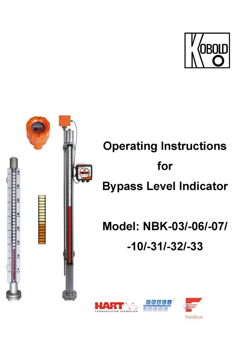
Kobold NBK-01 User manual

Operating Instructions
for
Bypass Level Indicator
with Threaded Connection
Model: NBK-01

NBK-01
page 2 NBK-01 K05/0322
1. Contents
1.Contents ........................................................................................................ 2
2.Note .............................................................................................................. 3
3.Instrument Inspection .................................................................................... 3
4.Regulation Use ............................................................................................. 4
4.1Bypass Measuring Tube System ......................................................... 4
4.2Electrical Limit Switches NBK-R .......................................................... 4
4.3Transmitter 00T ................................................................................... 4
5.Operating Principle ........................................................................................ 5
6.Mechanical Connection ................................................................................. 6
7.Electrical Connection .................................................................................... 8
7.1Limit contacts NBK-R ........................................................................... 8
7.2Transducer: Magnetostrictive transducer with 4-wire transmitter ......... 9
8.Commissioning............................................................................................ 10
9.Trouble Shooting ......................................................................................... 11
10.Maintenance ............................................................................................... 11
11.Technical Information .................................................................................. 12
12.Order codes ................................................................................................ 13
13.Dimensions ................................................................................................. 14
14.EC Declaration of Conformance ................................................................. 15
Manufactured and sold by:
Kobold Messring GmbH
Nordring 22-24
D-65719 Hofheim
Tel.: +49(0)6192-2990
Fax: +49(0)6192-23398
E-Mail: [email protected]
Internet: www.kobold.com

NBK-01
NBK-01 K05/0322 page 3
2. Note
Please read these operating instructions before unpacking and setting the unit into
operation. Follow the instructions precisely as described herein.
The instruction manuals on our website www.kobold.com are always for currently
manufactured version of our products. Due to technical changes, the instruction
manuals available online may not always correspond to the product version you
have purchased. If you need an instruction manual that corresponds to the
purchased product version, you can request it from us free of charge by email
([email protected]) in PDF format, specifying the relevant invoice number and
serial number. If you wish, the operating instructions can also be sent to you by
post in paper form against an applicable postage fee.
The devices are only to be used, maintained and serviced by persons familiar with
these operating instructions and in accordance with local regulations applying to
Health & Safety and prevention of accidents.
When used in machines, the measuring unit should be used only when the
machines fulfil the EC-guidelines.
Classification according to Pressure Equipment Directive 2014/68/EU
NBK-01
Cate
g
or
y
assi
g
nment for dan
g
erous media
(
from dia
g
ram 1
)
Density
[kg/dm³]
PN
[bar]
Category ML
[mm]
Category ML
[mm]
Category ML
[mm]
NBK-01
1,0
16
← Art.4, Para.
3← ≤317 ← Cat. I → 945 ← Cat. II → 4711
0,9/0,8/0,7/
0,6/0,54
≤207 835 4600
Cate
g
or
y
assi
g
nment for not dan
g
erous media
(
from dia
g
ram 2
)
Density
[kg/dm³]
PN
[bar]
Category ML
[mm]
Kategorie ML
[mm]
Category ML
[mm]
NBK-01
1,0
16
← Art.4, Para.
3← ≤945 ← Cat. I
→5500 ← Cat. II → 24795
0,9/0,8/0,7/
0,6/0,54
≤835 5500 24685
ATTENTION! If the calculated bypass length is exactly within the range limit, then the stricter test
method must be used.
3. Instrument Inspection
Instruments are inspected before shipping and sent out in perfect condition.
Should damage to a device be visible, we recommend a thorough inspection of the
delivery packaging. In case of damage, please inform your parcel service /
forwarding agent immediately, since they are responsible for damages during
transit.
Scope of delivery:
The standard delivery includes:
Bypass Level Indicator model: NBK-01…

NBK-01
page 4 NBK-01 K05/0322
4. Regulation Use
Any use of the Bypass level Indicator, model: NBK, which exceeds the
manufacturer’s specification, may invalidate its warranty. Therefore, any resulting
damage is not the responsibility of the manufacturer. The user assumes all risk for
such usage.
The NBK Bypass Level Indicator is used for continuous measurement, indication,
and monitoring of liquids in tanks, vessels, reservoirs, basins etc. The indication
occurs via a magnetically coupled roller indicator.
4.1 Bypass Measuring Tube System
The bypass tube is attached at the side of the vessel with a connecting flange or a
threaded pipe. The installation position is always vertical. The NBK should only be
used for liquids with the medium density specified on the nameplate. Otherwise the
indication will deviate (float too high or submerged).
Vessel inner pressure and medium temperature should not exceed the specified
maximum values, as this can lead to the destruction and malfunction of the bypass
system. It is imperative that the materials used are compatible with the liquid being
measured.
Proper operation is also impaired by:
high degree of soiling
suspended solids
crystallisation
ferrite particles
4.2 Electrical Limit Switches NBK-R
The optional electrical limit switches serve to signal a preset level.
4.3 Transmitter 00T
A magnetostrictive transmitter can be mounted outside the bypass tube to
teletransmit the level. A continuous standard signal of 4-20 mA is output by means
of a fitted transmitter.

NBK-01
NBK-01 K05/0322 page 5
5. Operating Principle
Kobold Bypass Level Indicators are used for continuous measurement, display and
monitoring of liquid levels. The bypass tube is attached onto the side wall of the
vessel.
According to the law of communicating tubes the level in the bypass tube equals
the level in the vessel. A float with embedded circular magnets in the bypass tube
follows the liquid level and transfers it in a non-contacting manner to a display or a
monitoring device fitted outside the tube. The following indication and monitoring
devices are available:
Magnetic roller indicator
As the float passes by, the red/white rollers are rotated in succession by 180°
around their own axes. The rollers change from white to red as the level rises and
from red to white as the level falls. The advantage of ball displays is the higher
protection category, good visibility of 180 ° and higher vibration resistance with
filled version. The level in a tank or a mixer is continuously displayed as a red
column, even when the power supply fails.
Transmitter
A magnetostrictive transmitter can be mounted outside the bypass tube to
teletransmit the level. A continuous standard signal of 4-20 mA is output by means
of a fitted transmitter.
Limit contacts
One or more reed contacts for limit-value acquisition or also for level control can
be attached to the bypass tube.

NBK-01
page 6 NBK-01 K05/0322
6. Mechanical Connection
Remove the bottom flange from the
bypass tube, and insert the
cylindrical float in the NBK bypass
tube with the designation "TOP"
upturned. Reposition the gasket
and close the bottom flange again;
firmly tighten with screws.
Mount the bypass tube to the
vessel to be monitored via the
process connection and seal with
an appropriate device. Normally it
is sufficient to fix the complete NBK
with both process connections.
However the NBK should be
subjected to constant shock or
strong vibrations it is
recommended that the instrument
is secured with rubber-damped
tube clips. No welding is allowed on
the bypass tube.
Mount and tighten the magnetic
roller indicator - if not already
mounted - on the bypass tube with
the two provided ribbon clamps.
Mount and tighten the reed switch
- if available - on the bypass tube at
the opposite side of the roller
indicator with the provided ribbon
clamps (ex contact: two ribbon
clamps). The height of the switch
contacts may be selected at will.
The cable connection must point
downwards. The switch must be
attached close to the bypass tube.
The switching function of the switch
is impaired by an enlarged air gap.

NBK-01
NBK-01 K05/0322 page 7
Magnetostrictive Transmitter
Mount and tighten the remote sensor - if
available and not already mounted - on the
bypass tube with the ribbon clamps. The
remote sensor must fully cover both process
connections. The cable terminal box is
situated at the top.

NBK-01
page 8 NBK-01 K05/0322
7. Electrical Connection
7.1 Limit contacts NBK-R
Attention!
Observe the allowed electrical ratings for the limit switch.
Maximum values
NBK-R
Standard contact
Switching capacity: 60 W/VA
Switchin
g
current: 1
A
Switching voltage: 230 V
AC/DC
Install the switch (if available) according to the diagram and
connect it to the electrical controller.
When switching inductive loads, such as contactors, relays,
etc., electrical limit values should not, also temporarily, be
exceeded by e.g. voltage peaks. The use of a contact
protection relay is recommended to avoid overloading the
reed contacts.

NBK-01
NBK-01 K05/0322 page 9
7.2 Transducer: Magnetostrictive transducer with 4-wire transmitter
Ensure that the electrical supply lines are powerless.
To avoid faults caused by electrical fields from other circuits, the cables should not
be installed adjacent to other high voltage power lines.
Unscrew cover and run supply lines through cable gland.
Connect the remote sensor to the electronics according to the following wiring
diagram.

NBK-01
page 10 NBK-01 K05/0322
8. Commissioning
Because of the setting behaviour of seals, all screw connections must be
retightened.
Fill vessel and switch on electrical controller, if available. If there are gate valves
between bypass process connection and tank, first slowly open the upper valve
(pressure equalisation) and then the lower valve (liquid side). If vent and drain
valves have been installed, close them before filling.
The liquid that now enters the bypass tube raises the float until the level between
tank and bypass tube is balanced. The roller indicator indicates the liquid level.
Commissioning electrical reed switches NBK-R
Function of switches
All switches have three connection poles (black (2), blue (1) and brown (3)).
The black wire (2) is the common pole for both switching functions
(N/C and N/O contact).
The float must pass the switch once in both directions so that the switching function
is in line with the terminal connection diagram and table below.
These instructions are often ignored when an alarm lamp is connected directly with
the result that the alarm lamp incorrectly indicates a fault.
When the switch has been passed, it is ready for operation and requires no
maintenance.
black
(
2
)
/ blue
(
1
)
black
(
2
)
/ brown
(
3
)
float above open closed
float below closed open
Hysteresis
Hysteresis is the difference between contact closing
and opening points. A hysteresis of approximately
15 mm float travel is achieved by factory tuning of the
float magnet and contact strength.
Table of contents
Other Kobold Measuring Instrument manuals

Kobold
Kobold DRF34 Series Installation instructions

Kobold
Kobold Heinrichs HPC User manual

Kobold
Kobold DFT Series User manual

Kobold
Kobold ZOE-ZB**FB series User manual

Kobold
Kobold NMF User manual

Kobold
Kobold OMG User manual

Kobold
Kobold NSC User manual

Kobold
Kobold DWU 5 Series User manual

Kobold
Kobold Heinrichs K12 User manual

Kobold
Kobold OMS User manual

Kobold
Kobold DUC-ZUWD User manual

Kobold
Kobold KEP-2 User manual

Kobold
Kobold MIM Series User manual

Kobold
Kobold NMT User manual

Kobold
Kobold DAF-11 Series User manual

Kobold
Kobold DUK User manual

Kobold
Kobold NBK-04 User manual

Kobold
Kobold NPF User manual

Kobold
Kobold REG User manual

Kobold
Kobold DAG-A3T User manual