
Kobold OMS User manual
Operating Instructions
for
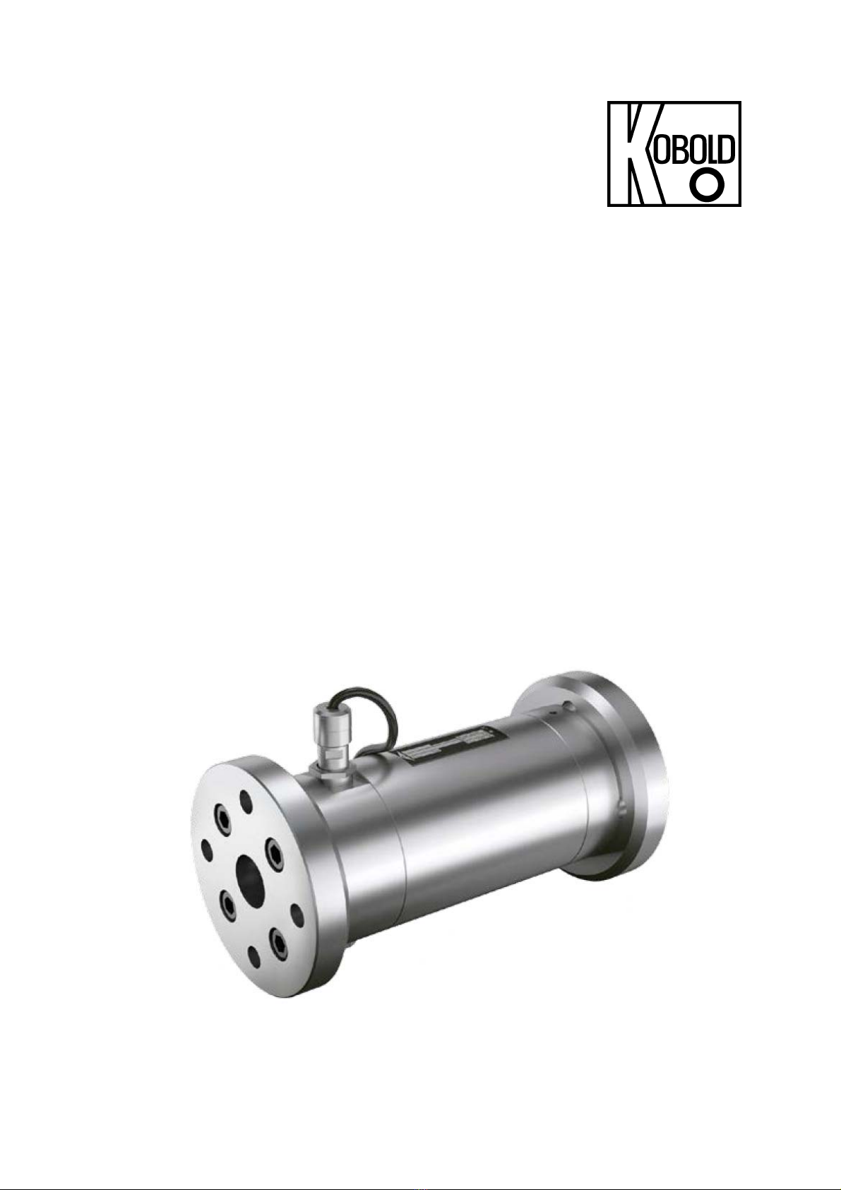
Screw-Type Volumetric Flow Meter
Model: OMS

OMS
page 2 OMS K01/0922
1. Contents
1.Contents ........................................................................................................ 2
2.Note .............................................................................................................. 3
3.Instrument Inspection .................................................................................... 3
4.General Information ...................................................................................... 4
5.Regulation Use ............................................................................................. 4
6.Warranty ....................................................................................................... 4
7.Operating Principle ........................................................................................ 5
8.Mechanical Connection ................................................................................. 6
9.Electrical Connection .................................................................................... 7
10.Disassembly and Assembly .......................................................................... 9
10.1Servicing .............................................................................................. 9
11.Start up ....................................................................................................... 16
12.Troubleshooting .......................................................................................... 17
13.Maintenance ............................................................................................... 18
14.Technical Information .................................................................................. 19
15.Order Details ............................................................................................... 21
16.Dimensions and Weights ............................................................................ 22
17.Pressure loss diagram ................................................................................ 24
18.Disposal ...................................................................................................... 25
19.Appendix ..................................................................................................... 26
19.1Tightening torque for screws with metric screw threads and head
contact surfaces ................................................................................. 26
19.2Tightening torques for screw plugs with thread measured in inches
and elastomer seal ............................................................................ 26
19.3Tightening torques and widths for threaded rings .............................. 27
20.EU Declaration of conformance .................................................................. 28
Manufactured and Sold by:
Kobold Messring GmbH
Nordring 22-24
D-65719 Hofheim
Tel.: +49(0)6192-2990
Fax: +49(0)6192-23398
E-Mail: [email protected]
Internet: www.kobold.com

OMS
OMS K01/0922 page 3
2. Note
Please read these operating instructions before unpacking and putting the unit
into operation. Follow the instructions precisely as described herein.
The instruction manuals on our website www.kobold.com are always for currently
manufactured version of our products. Due to technical changes, the instruction
manuals available online may not always correspond to the product version you
have purchased. If you need an instruction manual that corresponds to the
purchased product version, you can request it from us free of charge by email
([email protected]) in PDF format, specifying the relevant invoice number and
serial number. If you wish, the operating instructions can also be sent to you by
post in paper form against an applicable postage fee.
The devices are only to be used, maintained and serviced by persons familiar
with these operating instructions and in accordance with local regulations
applying to Health & Safety and prevention of accidents.
When used in machines, the measuring unit should be used only when the
machines fulfil the EC-machine guidelines.
as per PED 2014/68/EU
In acc. with Article 4 Paragraph (3), "Sound Engineering Practice", of the
PED 2014/68/EU no CE mark.
Diagram 8, Pipe, Group 1 dangerous fluids
3. Instrument Inspection
All Instruments are inspected before shipping and sent out in perfect condition.
Should damage to a device be visible, we recommend a thorough inspection of
the delivery packaging. In case of damage, please inform your parcel service /
forwarding agent immediately, since they are responsible for damages during
transit.
Scope of delivery:
The standard delivery includes:
Screw-Type Volumetric Flow Meter, model: OMS-...

OMS
page 4 OMS K01/0922
4. General Information
lt is important that all staff concerned with the unit read the operation and
maintenance manual prior to start up of the unit.
The user is responsible for taking the precautions outlined in this manual
This screw-volumeter should not be operated outside of the data given on the
type plate. Any differences require confirmation from us.
It is not possible to put all the information you may require in the manual.
Should you require any special information, please contact us.
Depending on the operating conditions, wear, corrosion or age of the unit, its
specified attributes may be limited. It is therefore essential that the unit is
periodically maintained. The user must replace all parts which would not
guarantee a long operating life or trouble-free operation. If the unit operates
unusually or if damage is observed, further operation must be discontinued
Installations which could lead to personal injury and/or material failure should
be equipped with an alarm system and/or bypass. This system should be
checked periodically.
5. Regulation Use
Any use of the Helical Volume-meter, model: OMK-..., which exceeds the
manufacturer’s specifications, may invalidate its warranty. Therefore, any
resulting damage is not the responsibility of the manufacturer. The user assumes
all risk for such usage.
6. Warranty
The warranty is according to our terms of delivery. Repairs during the guarantee
period must be carried out only by user or any other person authorised by us and
in accordance with our agreement and instructions.

OMS
OMS K01/0922 page 5
7. Operating Principle
The measuring principle of the KOBOLD screw-
volumeter is positive displacement.
The flow of the fluid to be measured causes the
measuring spindles M to rotate. With each
rotation an exact volume is given. These
rotations are being transmitted to the display A
by the pole wheel P and pick up I.
There the volume can be shown in any unit of
measurement.

OMS
page 6 OMS K01/0922
8. Mechanical Connection
Mountin
g
position: an
y
Flow direction: both directions are possible, preferable flow D according the
identification plate.
Minimum pressure:
The meter back pressure at the outlet fitting should be kept
higher than 0,1 bar (1.5 PSIG). In no case may the medium
freely run out of the flow meter. If necessary, install a valve
at the meter outlet to generate the appropriate back
pressure.
Unclean medium: Filtration with max. 0,3 mm (30 Micron) mesh width is
required.
Foreign substance: The pipe system must be free from welding slag, cuttings,
as the
y
can block and dama
g
e the flow meter.
Over pressure
valve:
A blocked flow meter stops the complete flow of the
medium, therefore, depending on the application, a
pressure relief valve is required.
Fastening: Must be installed with piping fully supported at the inlet and
outlet and properly aligned to prevent stresses on the flow
meter pipe thread connection.
Pipe thread con-
nection:
Storage:
The thread length of the pipe should not be longer than the
thread length of the flowmeter (Stricture of the flow-
diameter, damaging of internal parts).
Improper storage may cause corrosion and seizing of
internal parts.

OMS
OMS K01/0922 page 7
9. Electrical Connection
The screw-type volumeters are set up, tested and delivered with an integrated dry
sleeve.
The purchaser must screw the pulse generator cartridge into the dry shell using
the knurled nut and spring.
Caution! The dry shell must not contain any foreign matter. The
spring must be able to push the pulse generator cartridge fully into
the front side of the dry shell.
The free cable ends are connected to a display unit. When connecting, please
comply with the terminal diagram and technical data. Further technical data can
be found in the additional operating instructions "Pulse generator of the OM
series".
Caution! The sensor system (sensor, measuring transducer and
wires) must not be located in the vicinity of powerful
electromagnetic field pulses, such as those emanating from
overhead power lines, electric motors, frequency converters etc.
That could lead to incorrect measurements or even cause serious
damage to the sensor system.

OMS
page 8 OMS K01/0922
Mounting and dismounting
The sensors consist of a sensor cartridge E that is screwed into the relevant dry
shell G using the knurled ring R and spring.
During operation, the sensor insert E can also be changed when the system is
under pressure and without fluid leaking out.
The dry shell G was built in, screwed in and tested as a unit with the sensor
cartridge E at the KOBOLD factory. The dry shell G must not be moved out of
position because that might cause the sensor signal to be lost or the volumeter to
be damaged or functionally impaired.
OM.../44
Caution: If the dry shell G is out of position, this is indicated by
the red sealing point. If the sealing point is damaged, then no
warranty for the volumeter can be assumed.

OMS
OMS K01/0922 page 9
10. Disassembly and Assembly
This work is only to be carried out by trained personnel. The manual is only
intended as an aid for performing the work.
If the spindle set or the measurement housing is replaced, the volumeter must be
recalibrated!
10.1 Servicing
Dangers during servicicng
The following safety instructions must be observed strictly:
Have all work only carried out by authorized qualified personnel.
To ensure the measuring precision, the measuring unit may only be replaced
by the manufacturer.
Before beginning work, let the flowmeter cool down slowly to the ambient
temperature. Avoid rapid temperature changes
Pumped liquids can be hot, poisonous, combustible and caustic.
Observe the tightening torques, see Appendix, chapter 19.
Observe the operating instructions and data sheets of the sensors.
10.1.1 Removing seals and bearings OMS-20/OMS-25
Personal qualification:
Fitter
Personal protective
equipment
Work clothing
Protective gloves
Safety boots
Aids:
Extractor
Requirement:
Flowmeter removed from system
Completion consisting of socket screws, flanges and seals removed
Pick up inserts removed
Remove the socket screws 915.1 and 915.2, take off the end covers 070.1
and 070.2
Remove the O-rings 739.1, 739.2 and 739.5** (1 x per pick up hole).

OMS
page 10 OMS K01/0922
Pull the distance sleeve 039 together with the screw set out of the
measuring housing 128.
Remove the circlips 869.2 and 869.4 from the measuring screw large
672.1 and measuring screw small 672.2.
Screw out the socket screws 915.6 and 915.7 and remove the wedge lock
washers 904.1, 904.2 and supporting rings 064.1*** (only OMS-032)
064.2.
Screw the socket screw 915.6 completely back in, in order to pull the pole
wheel 259 and distance ring 056 from the measuring screw large 672.1 by
using an extractor. Remove the socket screw 915.6 again.
Pull the ball bearings 817.1, 817.2, 817.3 and 817.4 from the measuring
screws by using the ex- tractor.
10.1.2 Installing seals and bearings OMS-20/OMS-25
Personal qualification:
Fitter
Personal protective equipment: Work clothing
Protective gloves
Safety boots
Table of contents
Other Kobold Measuring Instrument manuals

Kobold
Kobold NBK-16 User manual

Kobold
Kobold DPL User manual

Kobold
Kobold DRS 0 Series User manual

Kobold
Kobold HND-F215 User manual

Kobold
Kobold VKP-1020 Series User manual

Kobold
Kobold SZM User manual

Kobold
Kobold KSM User manual

Kobold
Kobold ZUB-MANS-KON1/2 User manual

Kobold
Kobold KEC-2 User manual

Kobold
Kobold SMN-1150 H Series User manual

Kobold
Kobold DRG Series User manual

Kobold
Kobold SMO Series User manual

Kobold
Kobold KFR-1000 Series Installation instructions

Kobold
Kobold SMV User manual

Kobold
Kobold KDF-9 User manual

Kobold
Kobold NBK-04 User manual

Kobold
Kobold KMT-1 User manual

Kobold
Kobold KAL-K User manual

Kobold
Kobold HND-P239 User manual

Kobold
Kobold NBK-03 User manual


