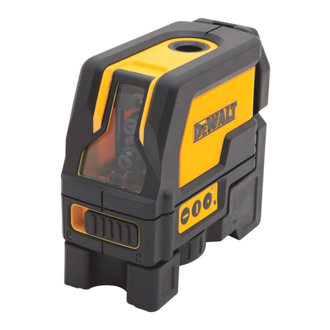
DeWalt DW0300 User manual

Please read these instructions before operating the product.
www.DEWALT.com
DW0300
Stud Sensor
E
PT
ES
F
DEWALT MPP2 STUD SENSOR - DW0300 - User Manual - NA - MAY 2019.indd 1 5/21/2019 3:37:21 PM

A
1
3
2
4
5
6
Figures
2
< 25%
DEWALT MPP2 STUD SENSOR - DW0300 - User Manual - NA - MAY 2019.indd 2 5/21/2019 3:37:21 PM

C
B
1
2
3
DEWALT MPP2 STUD SENSOR - DW0300 - User Manual - NA - MAY 2019.indd 3 5/21/2019 3:37:22 PM

D
Figures
4
DEWALT MPP2 STUD SENSOR - DW0300 - User Manual - NA - MAY 2019.indd 4 5/21/2019 3:37:25 PM

E
1
2
5
E
AC
AC
6” - 18”
12”
DEWALT MPP2 STUD SENSOR - DW0300 - User Manual - NA - MAY 2019.indd 5 5/21/2019 3:37:25 PM

F
6
E
~
~
DEWALT MPP2 STUD SENSOR - DW0300 - User Manual - NA - MAY 2019.indd 6 5/21/2019 3:37:29 PM

7
E
Contents
• Stud Sensor Information
• User Safety
• Battery Safety
• Installing AAA Batteries
• Using the Stud Sensor
• Maintenance
• Troubleshooting
• Service and Repairs
• Warranty
• Specications
Stud Sensor Information
The Stud Sensor DW0300 uses electronic signals to locate the center of
wood or metal studs, live AC wires, or metal objects (e.g., pipe) through
drywall or other common building materials.
PLEASE NOTE:
• The stud sensor will not detect objects in concrete, mortar, block, brick
work, plaster, carpeting, foil-faced materials, metallic surfaces, or ceramic
tile.
• The stud sensor will not detect plastic or PVC pipes.
Once the center of a wood or metal stud, or a metal object has been
detected in one pass across the surface, the Stud Sensor DW0300 turns on
the center LEDs and sounds an audible tone. A marking hole allows you to
easily note the current position on the wall.
User Safety
Safety Guidelines
The denitions below describe the level of severity for each signal word.
Please read the manual and pay attention to these symbols.
WARNING: Indicates a potentially hazardous situation which, if not
avoided, could result in serious injury.
CAUTION: Indicates a potentially hazardous situation which, if not
avoided, may result in minor or moderate injury.
NOTICE: Indicates a practice not related to personal injury which, if not
avoided, may result in property damage.
If you have any questions or comments about this or any DEWALT®
tool, go to www.DEWALT.com.
WARNING:
Read and understand all instructions. Failure to follow the
warnings and instructions in this manual may result in serious
personal injury.
SAVE THESE INSTRUCTIONS
WARNING:
The following label information can be found on your tool for your
safety.
WARNING:
If the equipment is used in a manner not specied by the
manufacturer, the protection provided by the equipment may
be impaired.
CAUTION:
Protect your eyes. Wear safety goggles.
WARNING:
This tool is not a measuring device and should not be used as
a substitute for a voltmeter.
WARNING:
The LED or Live Wire Detection symbol on the display is just an
indicator and in some situations the voltage detection option may
not accurately indicate the presence of voltage in a wall in the
event of internal device failure or improper operation, and therefore
should not be solely relied upon for identication of the presence
of hazardous voltages. Other evidence, such as construction
blueprints or visual identication of wiring or conduit entry points
should also be utilized.
Always follow proper safety practices and use a separate detection
method to verify a de-energized condition prior to commencing
work.
WARNING:
Always turn off AC power when working near wiring.
WARNING:
Shielded wires or wires in metal conduits, casings, metalized
walls, or thick, dense walls may not be detected.
CAUTION:
Use personal protective equipment. Always wear eye protection.
Depending on the work conditions, wearing protective equipment
such as a dust mask, non-skid safety shoes, hard hat, and hearing
protection will reduce the risk of personal injury.
IMPORTANT SAFETY NOTICE
Ensure proper detection of live wires. Always hold the Stud Sensor
DW0300 in the handle area only. Grasp between ngers and thumb while
making contact with your palm (Figure C1).
DEWALT MPP2 STUD SENSOR - DW0300 - User Manual - NA - MAY 2019.indd 7 5/21/2019 3:37:30 PM

8
E
Supplier’s Declaration of Conformity
47 CFR § 2.1077 Compliance Information
Unique Identier: DW0300
Responsible Party – U.S. Contact Information
DEWALT
701 East Joppa Road
Towson, Maryland 21286
www.DEWALT.com
FCC Statement
This equipment has been tested and found to comply with the limits for a
Class B digital device, pursuant to part 15 of the FCC Rules. These limits
are designed to provide reasonable protection against harmful interference
in a residential installation. This equipment generates, uses and can radiate
radio frequency energy and, if not installed and used in accordance with
the instructions, may cause harmful interference to radio communications.
However, there is no guarantee that interference will not occur in a particular
installation. If this equipment does cause harmful interference to radio or
television reception, which can be determined by turning the equipment off
and on, the user is encouraged to try to correct the interference by one or
more of the following measures:
- Reorient or relocate the receiving antenna.
- Increase the separation between the equipment and receiver.
- Connect the equipment into an outlet on a different circuit (not the circuit to
which the receiver is connected).
- Consult the dealer or an experienced radio/TV technician for help.
Canada, Industry Canada (IC) Notices
This Device complies with Industry Canada License-exempt RSS
standard(s). Operation is subject to the following two conditions: 1) this
device may not cause interference, and 2) this device must accept any
interference, including interference that may cause undesired operation of
the device.
Under Industry Canada regulations, this radio transmitter may only operate
using an antenna of a type and maximum (or lesser) gain approved for
the transmitter by Industry Canada. To reduce potential radio interference
to other users, the antenna type and its gain should be so chosen that
the equivalent isotropically radiated power (e.i.r.p.) is not more than that
necessary for successful communication.
Battery Safety
WARNING:
Batteries can explode, or leak, and can cause injury or re. To
reduce this risk:
• Carefully follow all instructions and warnings on the battery label and
package.
• Always insert batteries correctly with regard to polarity (+ and –), as
marked on the battery and the equipment.
• Do not short battery terminals.
• Do not charge disposable batteries.
• Do not mix old and new batteries. Replace all batteries at the same time
with new batteries of the same brand and type.
• Remove dead batteries immediately and dispose of per local codes.
• Do not dispose of batteries in re.
• Keep batteries out of reach of children.
Installing AAA Batteries
Load two new AAA batteries in the DW0300 stud sensor.
1. On the bottom of the stud sensor, lift up the latch (Figure B1) to
unlock the battery compartment cover.
2. Move the cover upward (Figure B2) and remove it once it separates
from the stud sensor.
3. Insert two new, high-quality AAA batteries, making sure to position the
-and +ends of each battery as noted inside the battery compartment
(Figure B3).
4. Place the cover back on the stud sensor (Figure B4).
• Insert the two pins at the top of the cover into the holes near the top of
the battery compartment.
• Slowly lower the cover and press down until the latch locks securely
on the stud sensor.
5. Press or to test the stud sensor.
• The stud sensor should sound one short beep. The Power LED
should turn on. All the other LEDs should illuminate for a second and
then turn off.
• Whenever you press or , the green Power LED should
illuminate to indicate that the batteries are good. If this LED blinks or
does not illuminate, change the batteries.
Using the Stud Sensor
The DW0300 stud sensor will help you nd wood or metal studs, AC
voltage, or metal objects (e.g., pipe) behind drywall.
• The stud sensor has two buttons. Use the bottom button (Figure A3) to
search for wood/metal studs or AC, and use the top button (Figure A2)
to search for metal objects (e.g., pipe).
• The stud sensor will detect wood studs through up to 1” (25mm) thick
drywall, and metal studs and AC voltage through up to 1.5” (38mm) thick
drywall.
• The stud sensor will detect a ferrous metal object (contains iron) up to 3”
(76.2mm) from the surface of the wall to the center of the object.
• The stud sensor will detect a non-ferrous metal object (e.g., copper) up to
2” (51mm) from the surface of the wall to the center of the object.
• When AC voltage is found, the stud sensor will sound short (alternating)
beeps and light the AC LED (Figure A5).
• When the center of a stud is found (or a metal object is nearby), the stud
sensor will sound one longer (constant) beep and light the center LEDs
(Figure A4).
• When live AC and the center of a stud are both found, the stud sensor will
alternate between the long and short beeps, and light the center LEDs
and the AC LED.
Finding a Stud
1. To hold the stud sensor, place your thumb on one side of the stud
sensor, your pointer finger and your palm over the center of the stud
sensor, and the rest of your fingers on the same hand on the other side
of the stud sensor (Figure C1).
2. Gently place the stud sensor flat against the wall and parallel to a door
or window on the same wall, which gives you an indication of how the
studs are positioned behind the wall (Figure C2).
DEWALT MPP2 STUD SENSOR - DW0300 - User Manual - NA - MAY 2019.indd 8 5/21/2019 3:37:31 PM

9
E
3. Without moving the stud sensor, use your pointer finger to press and
hold (Figure A3). WAIT 1 sec until all the LEDs (except the
Power LED) turn off.
4. While still pressing , SLOWLY move the stud sensor to the left or
the right on the wall.
5. As you move the stud sensor, watch the stud sensor LEDs and listen
for beeps.
• If lights on the right side of the stud sensor (Figure D1),
continue moving the stud sensor to the right to find the nearest stud.
As you get closer to the stud, will light (Figure D2).
• If lights on the left side of the stud sensor, continue moving the
stud sensor to the left to find the nearest stud. As you get closer to the
stud, will light.
• If live AC voltage is found within 6”-18” (.15m - .5m) of the stud
sensor’s current position, the AC LED will illuminate and you will hear
short beeps.
NOTE: Static electrical charges that can develop on drywall and
other surfaces will spread the voltage detection area many inches on
each side of the actual electrical wire. This can cause the stud sensor
to indicate that it has found live AC when it is not actually near an
electrical wire (Figure E1). To aid in locating the wire position, place
your other hand on the surface approximately 12” (30cm) from the
stud sensor (Figure E2), or hold the stud sensor ½” - 2” (13mm -
50mm) away from the wall surface.
6. When the center LEDs light and you hear a constant beep, the stud
sensor has found the center of a stud (Figure D3).
NOTE: If live AC voltage is found near the center of a stud, both the
AC LED and the center LEDs (Figure A4) will illuminate and the stud
sensor will sound the short alternating beeps (AC found) followed by a
longer constant beep (stud center found).
• STOP moving the stud sensor and continue to hold it at the current
position.
• STOP pressing .
7. Through the hole on the stud sensor (Figure D4) use a pencil to
mark the current position on the wall as the center of the stud.
8. To find another stud on the wall, repeat the same steps.
Finding Metal Objects
The stud sensor will let you know if a metal object (e.g., a pipe) is located
behind the wall within 3” (76.2mm) of the stud sensor. In metal detection
mode, the arrows do not indicate which direction to move the stud
sensor to nd metal.
1. To hold the stud sensor, place your thumb on one side of the stud
sensor, your pointer finger and your palm over the center of the stud
sensor, and the rest of your fingers on the same hand on the other side
of the stud sensor (Figure C1).
2. Position the stud sensor flat against the wall and parallel to a door or
window on the same wall, which gives you an indication of how the
studs are positioned behind the wall (Figure C2).
3. Without moving the stud sensor, use your pointer finger to press and
hold (Figure A2). After 1 sec all the LEDs (except the Power
LED) will turn off.
4. While still pressing , SLOWLY move the stud sensor to the left or
the right on the wall.
5. As you move the stud sensor, watch the stud sensor LEDs.
• When and light on the left and right sides of the stud sensor,
slowly move the stud sensor to the left or right to find the metal object
(Figure F1).
• When and light on the left and right sides of the stud sensor,
you will know that you are moving the stud sensor closer to the metal
object (Figure F2).
6. When the center LEDs (Figure A4) light and you hear a constant
beep, the stud sensor has found a metal object (Figure F3).
• STOP moving the stud sensor and continue to hold it at the current
position.
• STOP pressing .
7. Through the hole on the stud sensor (Figure F4) use a pencil to
mark the current position on the wall.
8. To find another metal object behind the wall, repeat the same steps.
Maintenance
• When the stud sensor is not in use, clean the exterior parts with a damp
cloth, wipe the stud sensor with a soft dry cloth to make sure it is dry.
• Although the stud sensor exterior is solvent resistant, NEVER use
solvents to clean the stud sensor.
• Store the stud sensor in a clean location at a temperature between -67 ˚F
(-55 ˚C) and 158 ˚F (70 ˚C).
Troubleshooting
The LED is Blinking
The battery power is low.
• Check the AAA batteries to make sure:
• Each battery is installed correctly, according to +and –listed inside
the battery compartment.
• The battery contacts are clean and free of rust or corrosion.
• The batteries are new, high-quality batteries to reduce the chance of
battery leakage.
• Make sure the AAA batteries are in proper working condition. If in doubt,
try installing new batteries.
The LED does not Turn On
If the power LED does not turn on, or the power LED turns on for 1
sec and then turns off, there is no battery power.
• Install two new, high-quality, name-brand AAA batteries in the stud sensor.
• Make sure each battery is installed correctly, according to +and –listed
inside the battery compartment.
DEWALT MPP2 STUD SENSOR - DW0300 - User Manual - NA - MAY 2019.indd 9 5/21/2019 3:37:33 PM

10
E
The Stud Sensor is not Finding Studs
• Make sure the batteries are working.
• Make sure you have placed the stud sensor on a wall made of drywall or
another common building material. The stud sensor will not work on walls
made of concrete, mortar, block, brick work, plaster, carpeting, foil- faced
materials, metallic surfaces, or ceramic tile.
• Make sure you have placed the stud sensor at against the wall, the stud
sensor is in a vertical position (parallel to a door or window), and you are
pressing and holding (Figure A3) as you move the stud sensor
SLOWLY against the wall.
• Make sure the wall is not too thick. The DW0300 stud sensor can be used
to detect wood studs on walls < 1” (25mm) thick or metal studs on walls <
1.5” (38mm) thick.
• Make sure the wall has a smooth surface.
• Make sure the temperature is within the specied Operating Range and
Relative Humidity.
The Stud Sensor is not Finding Metal Objects
• Make sure the batteries are working.
• Make sure you have placed the stud sensor on a wall made of drywall or
another common building material. The stud sensor will not work on walls
made of concrete, mortar, block, brick work, plaster, carpeting, foil- faced
materials, metallic surfaces, or ceramic tile.
• Make sure you have placed the stud sensor at against the wall, the stud
sensor is in a vertical position (parallel to a door or window), and you are
pressing and holding (Figure A2) as you move the stud sensor
SLOWLY against the wall.
• Make sure the wall is not too thick. The DW0300 stud sensor can be used
to detect Non-Ferrous Metal (e.g., copper) on walls < 2” (51mm) thick or
Ferrous Metal (contains iron) on walls < 3” (76.2mm) thick.
• Make sure the wall has a smooth surface.
• Make sure the temperature is within the specied Operating Range and
Relative Humidity.
Service and Repairs
Note: Disassembling the tool will void all warranties on the product.
To assure product SAFETY and RELIABILITY, repairs, maintenance and
adjustment should be performed by authorized service centers. Service
or maintenance performed by unqualied personnel may result in a risk of
injury. To locate your nearest DEWALT service center, go to www.DEWALT.
com.
Warranty
Go to www.DEWALT.com for the latest warranty information.
DEWALT MPP2 STUD SENSOR - DW0300 - User Manual - NA - MAY 2019.indd 10 5/21/2019 3:37:33 PM
Table of contents
Languages:
Other DeWalt Measuring Instrument manuals

DeWalt
DeWalt DW040 User manual

DeWalt
DeWalt DW077-XE User manual

DeWalt
DeWalt DW078 User manual

DeWalt
DeWalt DW03101 User manual

DeWalt
DeWalt DW03601 User manual

DeWalt
DeWalt DCE089G18 User manual

DeWalt
DeWalt DW0330S User manual

DeWalt
DeWalt DW074LR User manual

DeWalt
DeWalt DW080LGS User manual

DeWalt
DeWalt DW0165 User manual

DeWalt
DeWalt DW030PL-KR User manual

DeWalt
DeWalt LaserChalkLine DW088 User manual

DeWalt
DeWalt DW077 User manual

DeWalt
DeWalt DCE089G18 User manual

DeWalt
DeWalt LaserChalkLine DCE088G User manual

DeWalt
DeWalt DW030 User manual

DeWalt
DeWalt DW089 User manual

DeWalt
DeWalt DW080LRS User manual

DeWalt
DeWalt DCLE34020 User manual

DeWalt
DeWalt DW079KI User manual