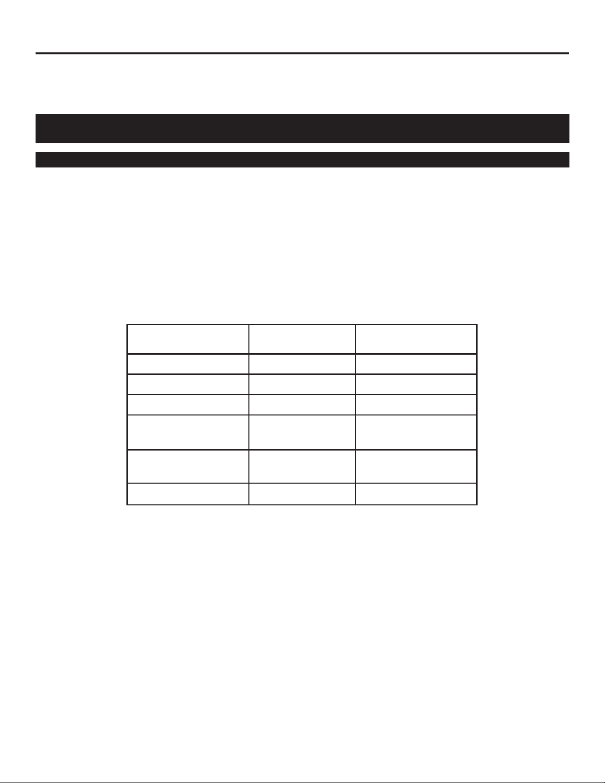
Body Description
3/8” MPT-std flow
1/2” MPT-std flow
3/4” MPT-std flow
1.0” MPT-std flow
3/8” MPT-low flow
1/2” MPT-low flow
Length
L
4.73”
5.09”
5.25”
5.65”
4.73”
5.09”
3/4” MPT-low flow
1.0” MPT-low flow
5.25”
5.65”
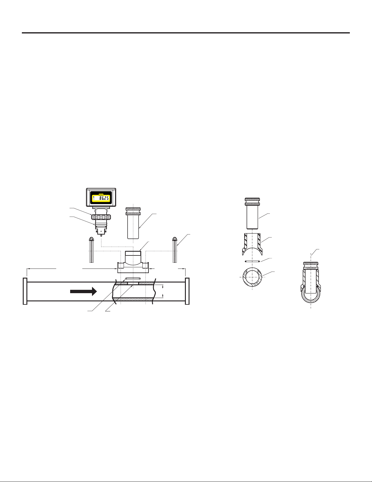
4.5 HOW TO INSTALL MOLDED PVC TEE
FITTINGS (TE)
!Select an area on the pipe as outlined in section 4.1.
!Remove the F-1000 sensor from the tee fitting. Do not glue the
TEE while the sensor is installed.
!Install the F-1000 tee fitting as you would any other plastic
pipe solvent weld (glue) fitting. Do not use too much glue.
Excessive glue may create a disturbance in the flow stream
which will effect the accuracy of the meter.
!The F-1000 can be mounted on horizontal or vertical runs of
pipe. Mounting at the twelve o'clock position on horizontal
pipe is recommended. Mounting anywhere around the diame-
ter of vertical pipe is acceptable, however, the pipe must be
completely full of water at all times. See figure 4, 5 and 6.
!Install the F-1000 sensor. Be sure two O-rings are located on
the sensor body. The O-rings have been lubricated at the
factory with silicone oil. Push the sensor assembly into the
saddle with a twisting motion. The notch on the sensor body
must fit into the slot on the saddle. Be sure the sensor is fully
inserted into the saddle. HAND TIGHTEN the union nut.
F-1000 Page 8 F-1000
Page 9
H
Nominal
Pipe Size
LFig. 11
Tee Fitting
Height
H
5.38”
5.38”
5.57”
5.57”
5.29”
5.29”
5.38”
5.57”
Nominal Pipe
Size
3/8”
1/2”
3/4”
1.0”
3/8”
1/2”
3/4”
1.0”
1”
1-1/2”
2”
4”
4-1/2”
4-3/4”
6”
6-5/8”
7-1/8”
Nominal Pipe
Size
Length
L
Height
H
Fig. 10
Molded in-line body
with M P T
Pipe
H
L
F-1000-RTRate - Totalizer
®
BLUE-WHITE INDUSTRIES
RESET
MODE
GALLONS PER MINUTE
F-1000-RTRate - Totalizer
®
BLUE-WHITE INDUSTRIES
RESET
MODE
GALLONS PER MINUTE
4.4 INSTALLING THE MOLDED IN-LINE FITTING (MI)
All molded in-line (MI) fittings have male American National Standard Taper Pipe Threads (MPT).
!Select an area on the pipe as outlined in section 4.1.
!Install the F-1000 as you would any other plastic pipe fitting. Be sure the inlet and outlet fittings are aligned
properly. Improper alignment of the fittings will put stress on the adapter connections and may cause
leaking or fitting damage. Do not over tighten the fittings. Use PTFE tape sealant only on the adapter
threads.
!The F-1000 can be mounted on horizontal or vertical runs of pipe. Mounting at the twelve o'clock position
on horizontal pipe is recommended. Mounting anywhere around the diameter of vertical pipe is accept-
able, however, the pipe must be completely full of water at all times. See figure 4, 5 and 6.
!Be sure the inlet and outlet plumbing is properly secured. The F-1000 is not designed to support the
weight of related piping. Improperly supported pipes will put stress on the adapter connections and may
cause leaking or fitting damage.
5.0 HOW TO OPERATE THE F-1000
Note: The calibrated units of measure such as GPM, LPM, M3H, GALLONS, LITERS, CUBIC METERS, ect., And the decimal point
location are pre-programmed at the factory to standard flow ranges (see chart). Any unit of measure can be factory programmed. Please contact
the factory for details.
!The meter is shipped from the factory with 2 AAA batteries installed.
!When measuring continuous flow (i.e. 24 hours per day, 7 days per week), do not operate the meter in the upper 25% of the calibrated flow
range. The paddle speed in these high flow ranges is fast. Damage to the paddle may occur if the meter is allowed to run continuously at the
high flow rate, especially with corrosive or abrasive fluids.
!Model F-1000-RB:The F-1000-RB is the basic rate meter. The meter will display the rate of flow from .01 through 999999 in any engineering
units. Some standard units of measure are GPM, GPH, GPD, LPM, LPH, LPD, M3H, etc.
!Model F-1000-TB:The F-1000-TB is the basic totalizer meter. The meter will display the total flow amounts from .01 through 999999 in any
engineering units. Some standard units of measure are GALLONS, LITERS, CUBIC METERS. Pressing and holding the RESET button
(located on the front panel) for at least 2.0 seconds resets the total to zero. This feature can be disabled -- see Fig. 12 below.
!Model F-1000-RT:The F-1000-RT is the rate and totalizer meter. The meter will display the flow rate amounts and the total flow amounts from
.01 through 999999 in any engineering units. Some standard units of measure are GALLONS PER MINUTE, GALLONS PER HOUR,
GALLONS PER DAY, LITERS PER MINUTE, LITERS PER HOUR, LITERS PER DAY, CUBIC METERS PER HOUR, CUBIC METERS PER
DAY. Pressing the RESET button (located on the front panel) toggles the display between flow rate and total flow. Pressing and holding the
RESET button for at least 2.0 seconds while the total flow value is displayed will reset the total to zero. This feature can be disabled -- see
Fig. 12 below.
21
-
+
Red wire
(Positive lead)
Black wire
(Negative lead)
Terminal blocks
(AC Coil sensor input)
Jumpers
(Front Panel Totalizer Reset
Enable/Disable)
Header pins
(Tail membrane connector)
Battery size: two AAA (1.5 V each)
Screw size: #4 x .50 Philip oval “A”
Mounting holes (x2)
Fig. 12
F-1000-RTRate - Totalizer
®
BLUE-WHITE INDUSTRIES
RESET
MODE
®
BLUE-WHITE INDUSTRIES
F-1000-RBFlow Rate Meter
GPM
GALLONS PER MINUTE
F-1000-TBFlow Totalizer
®
BLUE-WHITE INDUSTRIES
RESET
GALLONS
F-1000-RB F-1000-TB F-1000-RT
F-1000 Circuit Board
Jumper Not
Installed (open)
Jumper
Installed
JUMPER CONFIGURATION
Total flow reset
to zero Enable
(Factory default)
Total flow reset
to zero Disable
!The F-1000 is factory calibrated to ± 2% of full scale rate reading. When measuring total flow,
accumulated error over time must be considered. Accuracy is based on laboratory testing of nominal
pipe dimensions. Your actual accuracy will vary based on your actual pipe I.D. And other installation
factors.
!Due to increased wear on the paddle and axle, continuous operation at the upper 25% of the flow range is not
recommended.
6.0 FLOW RANGES