Xantech 780-80 User manual

IR Receivers
1
INSTALLATION INSTRUCTIONS
780-80
CFL FRIENDLY J-BOX INFRARED RECEIVER
The780-80isaCFL(compactfluorescentlight)friendly
version of the 780-10 J-box series IR receivers. It is
specifically designed to have great immunity to high
frequency ballasted CFL and overhead fluorescent
type infrared interference and to have exceptional IR
reception range. In addition, the 780-80 will operate in
direct sunlight!
It mounts easily into a single gang electrical J-box and
is supplied with mounting screws and a dark red lens
insert allowing the installer to use a Decorator-style
wall cover plate.
Fig. 1 The 780-80
Front
View Rear
View
FEATURES AND SPECIFICATIONS
•IR carrier frequency reception bandwidth: 30 to 60 kHz.
•IR Carrier Adjust: 32 to 56 kHz (allows output carrier frequency to be matched to a controlled component
for optimum performance).
•IR reception range: Up to 70 feet on axis (range depends on device being controlled and levels of IR
or EM interference).
•Nominal reception angle: 45 degrees off axis, unit vertical, 40 degrees off axis, unit horizontal with 50%
range reduction.
•Talk-back LED (red): Tests system for correct wiring as well as indicating infrared reception.
•Status LED (red):For systemON/OFF indication (requires 12 VDC source @ 10 mA).
•Connections: 4-screw terminal block on unit.
NOTE:
The 780-80 will not operate in 2-wire Phantom Power mode.
•Cable requirements for long lengths: 3 or 4-conductor/24 gauge solid or stranded wire up to 200', 22
gauge up to 600', 20 gauge up to 2000' and 18 gauge up to 5000' (unshielded OK).
•Maximum cable length: One mile with 18 gauge.
•Maximum current output: 100 mA peak.
• Use Xantech Connecting Blocks for connection to emitters.
•Power: 12 volts DC @ 20 mA. 781RG Power Supply (not included) powers up to ten 780-80's.
•Deep red lens (included): Fits decorator-style wall plate. (Replacement lens available. Order part
#3016400).
•Dimensions: 1-3/4" W x 4-1/8" H x 1-1/8" D.
FREQ
L
H
Talkback LED
Status LED
IR Carrier
Adjust
IR Receivers
+12V
STATUS
GND
IR OUT
780-80
IR RECEIVER
®

2
+12V
STATUS
GND
IR OUT
283M
Blink-IR™
Mouse Emitter
To 120 V AC
(unswitched)
781RG
Power Supply
789-44
Connecting Block
283M
Emitter
283M
Emitter
REMOTE ROOM MAIN ROOM
Hand Held
Remote
VCR
GND
IR
OUT
+12V
780-80
J-Box
IR Receiver
(rear view)
3-Conductor
Inter-room Cable
(unshielded OK)
780-80
IR RECEIVER
®
12VDC
+12 VDC
GND
STATUS
IR IN
EMITTERS
IR
RCVR
789-44
CONNECTING BLOCK
®
Satellite Receiver
AV Receiver
INSTALLATION
The 780-80 is intended to be wired to the IR INput
terminals of Xantech Connecting Blocks or other
Xantech devices.
• Use a 3 or 4-conductor cable (24 gauge up to
200', 22 gauge up to 600', 20 gauge up to
2000', 18 gauge up to 5000'), to run between
the remote room and main room locations.
• Make connections to a Xantech connecting
block, power supply and emitters as shown in
Fig. 2 - a typical basic system:
• While it is possible to make wired connections without the connecting block, it is not recommended. The
connecting block reduces installation time, helps to eliminate errors, allows easy troubleshooting and
permits easy system upgrades later, if needed.
• Input connections must be made as illustrated. To extend the Emitter wires to a more distant location,
you may splice in 2-conductor wire, in the wire gauges mentioned before, as needed.
• The 780-80 may be connected to any of the
Xantech Connecting Blocks, Controllers,
Interface modules, etc., that have +12VDC,
IR IN and GND terminals, such as the
CB12,789-44,791-44, 795-20, 796-20, 794
and 797 series, etc.
• 780-80's may be connected in parallel to
these terminals in any combination with
other Xantech 3 or 4-conductor IR receivers
or keypads (12 IR receivers max).
A more advanced system, using 780-80's and
a variety of other Xantech IR receivers con-
nected to a 791-44 Amplified Connecting
Block, is shown in Fig. 3.
Adjusting the IR Carrier Frequency
The 780-80 is factory set to an IR carrier
repeat frequency of 38 kHz. This will be
correct for the majority of installations. How-
ever, some manufacturer's components that you wish to control may use different carrier frequencies (such
as the RCA DSS satellite receivers that use 56 kHz). If such carrier frequencies fall within the range of 32
kHz to 56 kHz, you can adjust the 780-80 to match them for best range performance. The adjustment can
be made through a small opening on the front. See Fig. 4.
To adjust, proceed as follows:
1. First, try the 780-80 in a repeater system. If it works well with good range,
do not make any
adjustments!
2. If it does not work or has poor range (less than 15 feet), determine the IR carrier frequency of the
product you wish to control. Contact the manufacturer of the product, if necessary, to determine this
frequency.
3. Using a small blade type screwdriver (3/32" blade width max.), rotate the adjustment shaft until the slot
lines up with the desired frequency. Refer to Fig. 4.
780-80
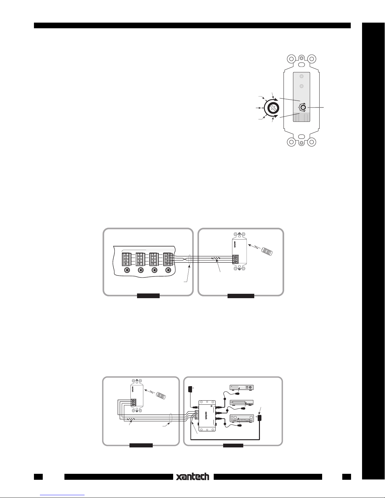
Fig.2 780-80 Basic IR Repeater System
Fig.3 780-80 IR Receivers in a Typical Multi-room System
283M
Blink-IR™
Mouse Emitter
To 120 V AC
(unswitched)
781RG
Power Supply
283M
Emitter
283M
Emitter
283M
Emitter
283M
Emitter
VCR
Cassette DecK
GND
+12V
490-00 Series
Micro Link™
IR Receivers
3-Wire
Cable
IR
OUT
GND
+12V
Red
Stripe
3-Wire
Cable
IR
OUT
GND
+12V
480-00
Dinky Link™
IR Receiver
Red
(or white)
Stripe
REMOTE ROOM 1
780-80
J-Box IR Receiver
780-80
J-Box IR Receiver
7 Foot 3-Conductor
Cable with Quick
Connect Stereo
Mini Plug
490-30
Series
Micro Link™
IR Receivers
MAIN ROOM, EQUIPMENT AREA, ETC.
REMOTE ROOM 2
REMOTE ROOM 3 REMOTE ROOM 4
GND
IR
OUT
+12V
3-Conductor
Room-to-
Room Cables
(Home Runs)
+12V
STATUS
GND
IR OUT
+12V
STATUS
GND
IR OUT
791-44
Amplified Connecting Block
780-80
IR RECEIVER
®
780-80
IR RECEIVER
®
Satellite Receiver
AV Receiver
CD Changer
+12 VDC
GND
EMITTERS
12 VDC
HIGH
IR
OUT
STATUS
IR IN
IR
RCVR
791- 44
AMPLIFIED
CONNECTING BLOCK
®
IR
OUT

IR Receivers
3
780-80
Fig.5
Fig. 4 IR Carrier Frequency Adjust-
IR Carrier
Adjust
Full CW
32 kHz
Full CCW
56 kHz
38 kHz
48 kHz
42 kHz
FREQ
L
H
NOTE: The frequency markings shown in Fig. 4 are approxi-
mate only. You may need to "fine tune" the adjustment for best
performance.
4. If you have products in the same IR system that have different
IR carrier frequencies, you will have to adjust the 780-80 to a
midway position. For example, some may operate at 38 kHz
and others at 56 kHz. In this case, set the adjustment to
approximately 47 kHz, a midway position just to the right of the
48 kHz marking in Fig. 4.
NOTE: Some products are more tolerant of compromised
frequency settings than others. You may have to "fine tune" the
adjustment to "favor" the least tolerant component for the best
performance of all units in the system.
Using the Status LED Indicator
The 780-80 includes a Status LED, located just below the Talkback
LED (see Fig. 1). This permits multi-room systems to have visible power ON/OFF indicators in the remote
rooms.
When used with a ZPR68 Six Zone-Eight Source Preamp, you would connect the terminal marked STATUS
on the 780-80 to the terminal marked STATUS (or CO) on the ZPR68 IR Zone Input, as part of the normal
4-wire hookup. See Fig. 5 below.
-In single zone systems, the Status LED could show the ON/OFF status of an A/V receiver.
• To do this, you would plug a 12V adapter, such as the Xantech 786-00 Power Supply, into the
switched
AC Outlet of the A/V receiver. The 12V leads are then connected between the STATUS and
GNDterminals on the 789-44 ("+" to STATUS, "–" to GND). See Fig. 6.
• You may reduce the brightness of the Status LED by placing a resistor in series with the positive lead. Use
a resistor value that achieves the desired brightness level (usually 1k Ohm to 3.3k Ohm, 1/8 watt).
Fig.6
ZONE CONTROL - IR INPUTS
+12V
GND
STATUS
IR IN
+12V
STATUS
GND
IR OUT
Hand Held
Remote
GND
IR OUT
+12V
780-80
J-Box
IR Receiver
(rear view)
4-Conductor
Inter-room Cable
(unshielded OK)
MAIN ROOM REMOTE ROOM
STATUS
V
G
ST
S
Add resistor in series
with Status line to
adjust brightness, if required.
(See text near Fig. 6).
780-80
IR RECEIVER
ZPR68-10
Zone Control - IR Inputs section
®
+12V
STATUS
GND
IR OUT
283M
Blink-IR™
Mouse Emitter
To 120 VAC
(unswitched)
781RG
Power Supply
283M
Emitter
283M
Emitter
Hand Held
Remote
VCR
GND
IR OUT
+12V
780-80
J-Box
IR Receiver
(rear view)
4-Conductor
Inter-room Cable
(unshielded OK)
STATUS
Positive Side ("+")
786-00
Power Supply
(12V at 10 mA)
Plug into
Switched AC Outlet
on A/V Receiver
(see text)
Add resistor in series
with Status line to
adjust brightness, if desired.
(See text, this page).
REMOTE ROOM MAIN ROOM
–+
789-44
Connecting Block
780-80
IR RECEIVER
®
12VDC
+12 VDC
GND
STATUS
IR IN
EMITTERS
IR
RCVR
789-44
CONNECTING BLOCK
®
Satellite Receiver
A/V Receiver

4
APPLICATION PRECAUTIONS
The 780-80 is designed with special circuitry so that is has great immunity to infrared interference caused
by CFL (compact fluorescent light) and other types of high frequency electronically ballasted fluorescent
lights. Because of this, the following precautions must be taken into consideration when using these special
IR receivers:
1.
Do not use more than one 780-80 in a given room or area!
If two or more 780-80's, (or other Xantech CFL friendly IR receiver) receive the same IR signal
simultaneously, the system will not respond.
2.
The 780-80 (or other Xantech CFL friendly IR receivers) will not operate with Xantech products that
use 679 and RC16 Programmer commands!
This includes models 670, 671, 676, 677, 680, 686 and RT16. For installations using these products,
use standard Xantech IR Receivers, such as the 291, 480, 490, and 780-10 series.
3.
The 780-80 (or other Xantech CFL friendly IR receivers) do not have much improvement in
operation over the standard Xantech IR Receivers in the presence of magnetically ballasted (60
Hz) fluorescent lighting.
You may choose to use the CFL friendly units in most applications anyway, since they will have
superior rejection to other types of IR interference that may exist in the same installation.
4.
The 780-80 will not operate in 2-wire Phantom Power mode.
TROUBLE SHOOTING
1. The 780-80 has been designed to have high rejection of many sources of interference, such as:
• Compact Fluorescent, Neon or Halogen lights, Neon Art, and light dimmers.
• Direct or reflected sunlight.
• Infrared security sensors (active types).
• RF radiation from TV sets that may be close to the 780-80 IR Receiver.
However, in the presence of extremely intense interference from such sources, you may experience
a reduction in range between the handheld remote control and the 780-80. This may result in a
reduction from over 50 feet to 15 feet or so.
2. To improve the range under these conditions, you need to confirm the source of the interference. Do
this by temporarily turning off TV sets, etc., reducing the exposure of the 780-80 IR Receiver to direct
sunlight and turning off all lights, light dimmers and Infrared security systems. Then check to see if
the range improves.
When you have isolated the interfering source, it will be necessary to move either it or the 780-80 IR
Receiver to improve operation.
3. If the red Talk-Back LED on the 780-80 does not blink when you are sending IR commands from a
remote control, check the following:
• Make sure the power supply is plugged securely into a live 120V AC wall outlet.
• Be sure the +12V, OUTPUT and GND terminals are correctly connected to the respective +12V,
IR IN (or SIGNAL) and GND terminals on the connecting block.
• Check to see that all the emitters you are using are good, by substituting known good emitters.
• Models 283 and 286 series emitters will flash when the remote signal is sent, when the system is
operating correctly; Models 282 and 284 series will not. Use Xantech Model 179-99 Test IR to test
for presence of signal when using the 282 and 284 series emitters.
4. If you are sure the emitters are OK, but the components do not respond, reposition the emitter(s). They
may not be located directly over the component’s infrared receiving "window". Consult the owner's
manual of the unit or the manufacturer for the exact location of the infrared "window".
9-5-00
780-80
Table of contents
Other Xantech Receiver manuals

Xantech
Xantech Dinky Link DL85K User manual

Xantech
Xantech 48195D User manual

Xantech
Xantech ML85K User manual

Xantech
Xantech 29110D User manual

Xantech
Xantech Dinky Link 480B-30 User manual

Xantech
Xantech 291-455 User manual

Xantech
Xantech HL85 User manual

Xantech
Xantech HL25K User manual

Xantech
Xantech 78095 User manual

Xantech
Xantech ML85 User manual

Xantech
Xantech ML25 User manual

Xantech
Xantech 480-85 User manual

Xantech
Xantech 490-85 KITRP User manual

Xantech
Xantech HL95 User manual

Xantech
Xantech 490-85 User manual

Xantech
Xantech Dinky Link DL95M User manual

Xantech
Xantech 291-95 KITRP User manual

Xantech
Xantech WL85 User manual

Xantech
Xantech ML25K User manual

Xantech
Xantech Wall Link WL25 User manual