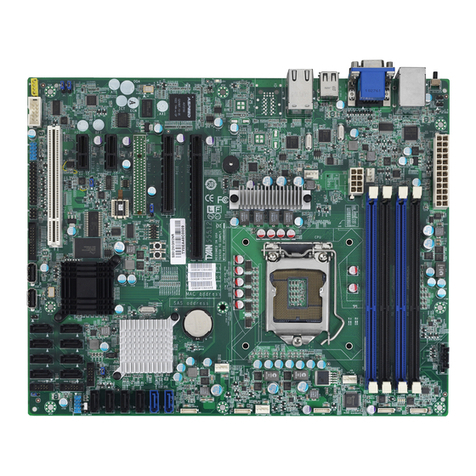
TYAN TRINITY 510 User manual

1
http://www.TYAN.com
Trinity 510 Manual
Revision 2.01
S2266
Copyright © TYAN Computer Corporation, 2001. All rights reserved. No part of this manual may be
reproduced or translated without prior written consent from TYAN Computer Corp.
All registered and unregistered trademarks and company names contained in this manual are
property of their respective owners including, but not limited to the following.
TYAN, Trinity 510 S2266 are trademarks of TYAN Computer Corporation.
Intel, Intel Pentium, combinations thereof are trademarks of Intel Corporation.
VIA, P4X266, P4X, and combinations thereof are trademarks VIA Technology Inc.
Award, Award BIOS are trademarks of Phoenix Technologies Ltd.
Microsoft, Windows are trademarks of Microsoft Corporation.
IBM, PC, AT, PS/2 are trademarks of IBM Corporation.
Winbond is a trademark of Winbond Electronics Corporation.
Micronics is a trademark of Micronics Corporation.
Portable Document Format (PDF) is a trademark of Adobe Corporation.
Information contained in this document is furnished by TYAN Computer Corporation and has been
reviewed for accuracy and reliability prior to printing. TYAN assumes no liability whatsoever, and
disclaims any express or implied warranty, relating to sale and/or use of TYAN products including
liability or warranties relating to fitness for a particular purpose or merchantability. TYAN retains the
right to make changes to product descriptions and/or specifications at any time, without notice. In
no event will TYAN be held liable for any direct or indirect, incidental or consequential damage,
loss of use, loss of data or other malady resulting from errors or inaccuracies of information
contained in this document.

2
http://www.TYAN.com
Table of Contents
Before you begin…
Chapter 1: Introduction
1.1 Congratulations
1.2 Hardware Specifications
1.3 Software Specifications
Chapter 2: Board Installation
2.1 Jumper Layout
2.2 Front Panel Connector
2.3 CMOS Reset
2.4 USB 1 and 2
2.5 Mounting the motherboard
2.6 Installing Memory
2.7 Installing the CPU and Cooling Fan
2.8 Connecting IDE/Floppy Drives
2.9 Installing Add-in Cards
2.10 Connecting PS/2, USB, Serial
2.11 Connecting the Power Supply
2.12 You’re Done!
Chapter 3: BIOS Setup
3.1 Main Setup
3.2 Advanced
3.3 Advanced CMOS Features
3.4 Advanced Chipset Features
3.5 Integrated Peripherals
3.6 VIA OnChip IDE Device
3.7 VIA OnChip PCI Device (Optional)
3.8 Super IO Configuration
3.9 Power Management Setup
3.10 IRQ/Event Activity Detect
3.11 IRQs Activity Monitoring
3.12 Frequency/Voltage Control
3.13 Exit and Saving
Chapter 4: Installing the Hard Drives
Chapter 5: System Resources
5.1 Beep Codes
5.2 Flash Utility
Appendix I: Memory Installation Instructions
Appendix II: Glossary
Technical Support
……………………………………………..Page 4
……………………………………………..Page 5
……………………………………………..Page 6
……………………………………………..Page 7
……………………………………………..Page 8
..……………………………………………Page 8
..……………………………………………Page 9
..…………………………………………Page 10
..…………………………………………Page 11
..…………………………………………Page 12
……………………………………………Page 15
……………………………………………Page 17
……………………………………………Page 18
……………………………………………Page 19
……………………………………………Page 20
……………………………………………Page 21
……………………………………………Page 22
……………………………………………Page 23
……………………………………………Page 24
……………………………………………Page 25
……………………………………………Page 26
……………………………………………Page 27
……………………………………………Page 29
……………………………………………Page 30
……………………………………………Page 31
……………………………………………Page 36

3
http://www.TYAN.com

4
http://www.TYAN.com
Before you begin…
Check the box contents!
The retail motherboard package should contain the following:
1x Trinity 510 motherboard
1x Pentium 4 Heatsink Mounting Kit
1x 34-Pin floppy drive cable
1x Ultra-DMA-100/66/33 IDE cable
1x Trinity 510 user’s manual
1x TYAN driver CD
1x I/O shield with 1 LAN port (optional)
If any of these items are missing, please contact your vendor/dealer for replacement before
continuing with the installation process.

5
http://www.TYAN.com
Chapter 1: Introduction
1.1 Congratulations!
You are now the owner of the TYAN Trinity 510 motherboard, the most reliable, high performance
motherboard for Pentium 4 processing. Designed to be portable as well as flexible, the Trinity 510
can fit into standard ATX chassis. This platform utilizes VIA’s high-performance P4X266 chipset,
enabling next generation application and platform support. Intel Pentium 4 processors (2GHz) are
supported. *Please see TYAN’s website for updates and information concerning CPU information
and support:
http://www.tyan.com
This integrated performance board is supported in an ATX form factor. Features of the Trinity 510
include onboard UltraDMA-100/66/33, optional integrated 100Mbit LAN, optional AC’97 Audio and
multiple boot options.
With both I/O and drive controller support onboard, five 32-bit PCI slots provide upgrade solutions
for future add-in cards. Optional integrated audio reduces overall system costs as well as optional
blazing fast 100Mbit LAN is integrated, providing instant high speed connectivity without any
hassles.
The Trinity 510 supports up to 2GB of unbuffered or registered PC1600/PC2100 DDR SDRAM.
Remember to visit TYAN’s Website at http://www.tyan.com. There you can find information on all
of TYAN’s products with FAQs, distributors list and BIOS setting explanations.
1.2 Hardware Specifications
Processor
•Single PGA478 socket
•Supports one Intel Pentium 4 processor
•Onboard VRM (VRM 9.0 spec)
•Front-side Bus support for 400MHz
Chipset
•VIA P4X266 chipset
•VT8753 north bridge and VT8233 south
bridge
•Winbond LPC Super I/O ASIC
Memory
•Four 2.5v 184-pin DDR DIMM sockets
•Supports up to 2GB of unbuffered or
registered PC1600/2100 DDR RAM
Expansion Slots
•One AGP 4X slot (1.5v design)
•Five 32-bit/33MHz PCI slots (5.0v, version
2.2)
•Total of six usable slots
Integrated Audio (optional)
•VIA VT1611A controller
•AC’97 audio codec
•One MIDI/Game port
•Line-in, Line-out and Mic-in ports
Integrated LAN (optional)
•Onboard network controller
•10/100Mbit data transfer rate
•3-pin Wake-on-LAN (WoL) header
Hardware Monitoring
•Winbond hardware monitoring ASIC
•CPU Temp, voltage and fan monitoring
BIOS
•Award 2Mb BIOS Flash ROM
•Supports APM v1.2 and ACPI v1.0
•User settings for hardware monitoring
•Auto-configure IDE drive types
•Multiple boot options
•DMI 2.0 compliant

6
http://www.TYAN.com
Integrated PCI IDE
•Dual-channel master mode
•Up to four Enhanced IDE devices
•Support for ATA-100/66/33 IDE and ATAPI
compliant devices

Integrated I/O
•One floppy connector supports up to two
drives
•Two 9-pin 16550-based serial ports
•One 25-pin SPP/ECP/EPP parallel port
•Two USB ports (two via optional cables)
•PS/2 keyboard and mouse ports
Form Factor
•ATX footprint (12” x 9.6”, 304.8mm x
243.84mm
•One 20-pin ATX power connector
•Stacked USB (two) ports and LAN (one-
optional) ports
•Stacked keyboard and mouse ports
Regulatory
•FCC DoC (declaration of Conformity)
•European Community of CE (declaration of
Conformity)
Note: The Trinity 510 S2266 accepts a standard ATX 2.01 power supply, with a minimum
output of 30 amps on the 5-volt line.
1.3 Software Specifications
OS Windows 9x/ME/NT/2000

7
http://www.TYAN.com
Chapter 2: Board Installation
Installation
You are now ready to install your motherboard. The mounting hole pattern of the Trinity 510
matches the ATX system board specifications. Your chassis should support a standard ATX
motherboard form factor.
How to install our products right… the first time
The first thing you should do is read this user’s manual. It contains important information which will
make configuration and setup much easier. Here are some precautions you should take when
installing your motherboard:
(1) Ground yourself properly before removing your motherboard from the antistatic bag.
Unplug the power from your computer power supply and then touch the power supply.
For the safest conditions, TYAN recommends wearing a static safety wrist strap.
(2) Hold the motherboard by its edges and do not touch the bottom of the board.
(3) Avoid touching the motherboard components, IC chips, connectors, and leads.
(4) Avoid touching memory module contacts and IC chips
(5) Place the motherboard on a grounded antistatic surface or on the antistatic bag from
which it came in.
Having reviewed the precautions above, the next step is to take the motherboard out of the
cardboard box and static bag, hold it by its edges and place it on a grounded antistatic surface,
component side up. Inspect the board for damage.
NOTE DO NOT APPLY POWER TO THE BOARD IF IT HAS BEEN DAMAGED

8
http://www.TYAN.com
2.1 – Jumper Section
Pin outs for certain connectors are available on the TYAN website: http://www.TYAN.com
2.2 – Front Panel Connector (J26)
17 15 13 11 9 7 5 3 1
18 16 14 12 10 8 6 4 2 1,3: HD LED
2,4: Power LED
5,7: Reset Switch
6,8: Power Switch
2.3 – CMOS Reset (J15)
1 2 1,2: Connect these two pins together to reset the CMOS settings in case an incorrect
setting causes system instability or you have forgotten your system/setup password or
have just flashed your BIOS.
-Power off the system and disconnect the power supply.
-Close pins 1 and 2 on J15
-Wait about 5 seconds
-Open pins 1 and 2 on J15
-Reconnect the power supply and power on the system
2.4 – USB 1 and 2 (JUSB1, JUSB2) - Optional
2 4 6 8 10
1 3 5 7 9 Use the USB1 and USB2 headers here for front panel USB connectors.

9
http://www.TYAN.com
Note: All other jumpers on the Trinity 510 are NOT user
adjustable.
Also, for the IDE and floppy connectors on the motherboard,
Pin 1 is located towards the inside of the motherboard
whereas the last pins are towards the edge of the board.
Please see page 28 for IDE pin diagram.

10
http://www.TYAN.com
2.5 Mounting the motherboard
Your chassis may include mounting hardware. If mounting hardware was included, you can use
the following examples to help you in stalling your motherboard into the chassis.
If your chassis has the studs integrated into the chasses wall, then you would only need to use
screws (possibly included with your chassis) to install the motherboard. See examples (Figure 2.0,
shown below for more details.
If the chassis includes mounting hardware without the studs pre-installed, then you will need to
install the motherboard using the mounting hardware as shown in the examples below.
Remember not to over tighten any of the screws, or you may risk breaking internal traces in the
surrounding area, or damage the motherboard in some other way.
Other examples of how to install your motherboard using other hardware (that may or may not
have been included with your chassis) are shown below.
chassis wall
stud
screw
motherboard
base
One solution for installing motherboardType of hardware Another solution Another solution
chassis wall
standoff
motherboard
base
chassis wall
standoff
motherboard
base
NOTE The diagrams above are only representative of a few solutions for installing a
motherboard into the chassis. The installation procedure for installing your
motherboard into the chassis may differ.
This manual suits for next models
1
Table of contents
Other TYAN Motherboard manuals

TYAN
TYAN Toledo q35T User manual

TYAN
TYAN TEMPEST I5000XT User manual

TYAN
TYAN Tomcat K8E-SLI S2866 User manual

TYAN
TYAN TOMCAT I7230B User manual

TYAN
TYAN S7070 User manual

TYAN
TYAN TOMCAT K8E User manual

TYAN
TYAN S5539 User manual

TYAN
TYAN TOMCAT I845GL User manual

TYAN
TYAN S1668 User manual

TYAN
TYAN 1.00 Technical manual

TYAN
TYAN THUNDER 2500 User manual

TYAN
TYAN S7065 User manual

TYAN
TYAN Trinity ATX Motherboard Tyan S1598 User manual

TYAN
TYAN S5515 User manual

TYAN
TYAN S5530 User manual

TYAN
TYAN TIGER LE User manual

TYAN
TYAN S5376 User manual

TYAN
TYAN 1.00 User manual

TYAN
TYAN S2692 User manual

TYAN
TYAN TIGER K8W User manual