EPOX MU-8KHA0010 User manual

TRADEMARK
All products and company names are trademarks or registered
trademarks of their respective holders.
These specifications are subject to change without notice.
Manual Revision 1.0
May 09, 2001
AnAn
AnAn
An AMD SocAMD Soc
AMD SocAMD Soc
AMD Sockk
kk
ketet
etet
et A PrA Pr
A PrA Pr
A Processor basedocessor based
ocessor basedocessor based
ocessor based
mainboard (100/133MHz)mainboard (100/133MHz)
mainboard (100/133MHz)mainboard (100/133MHz)
mainboard (100/133MHz)
SupporSuppor
SupporSuppor
Supports PC1600/PC2100 Memorts PC1600/PC2100 Memor
ts PC1600/PC2100 Memorts PC1600/PC2100 Memor
ts PC1600/PC2100 Memory Modulesy Modules
y Modulesy Modules
y Modules
User’User’
User’User’
User’ss
ss
s
ManualManual
ManualManual
Manual
$ &0


Table of Contents
Section 1 Introduction
Components Checklist ........................................ 1-1
Overview
AMD DuronTM & AthlonTM Processors ............. 1-2
Accelerated raphics Port .................................. 1-3
Ultra ATA66/100 ................................................. 1-3
Hardware Monitoring .......................................... 1-3
Mainboard Form-Factor ...................................... 1-4
I/O Shield Connector .......................................... 1-5
Power-On/Off (Remote) ..................................... 1-5
System Block Diagram........................................ 1-6
Section 2 Features
Mainboard Features ............................................. 2-1
Section 3 Installation
Mainboard Detailed Layout ................................. 3-2
Easy Installation Procedure
CPU Insertion ...................................................... 3-3
Jumper Settings ................................................... 3-5
System Memory Configuration .......................... 3-6
Device Connectors .............................................. 3-8
STR (Suspend To RAM) Function ....................... 3-11
Section 4 Award BIOS Setup
BIOS Instructions................................................. 4-1
Standard CMOS Setup ......................................... 4-2
Advanced BIOS Features..................................... 4-3
Advanced Chipset Features ................................. 4-7
Page

Integrated Peripherals ......................................... 4-10
Power Management Setup ................................... 4-14
PNP/PCI Configuration Setup .............................. 4-17
PC Health Status .................................................. 4-19
Frequency/Voltage Control .................................. 4-20
Defaults Menu ..................................................... 4-21
Supervisor/User Password Setting ...................... 4-22
Exit Selecting ........................................................ 4-23
Section 5 Driver Installation
Easy Driver Installation ........................................ 5-1
Appendi
Appendi A
HOST 5.1/6.03 Quick Users uide .................... A-1
Appendi B
POST Codes......................................................... B-1
Appendi C
EEPROM BIOS Remover ................................... C-1
Appendi D
Update Your System BIOS .................................. D-1
Introduction
Page 1-1
Section 1
INTRODUCTION
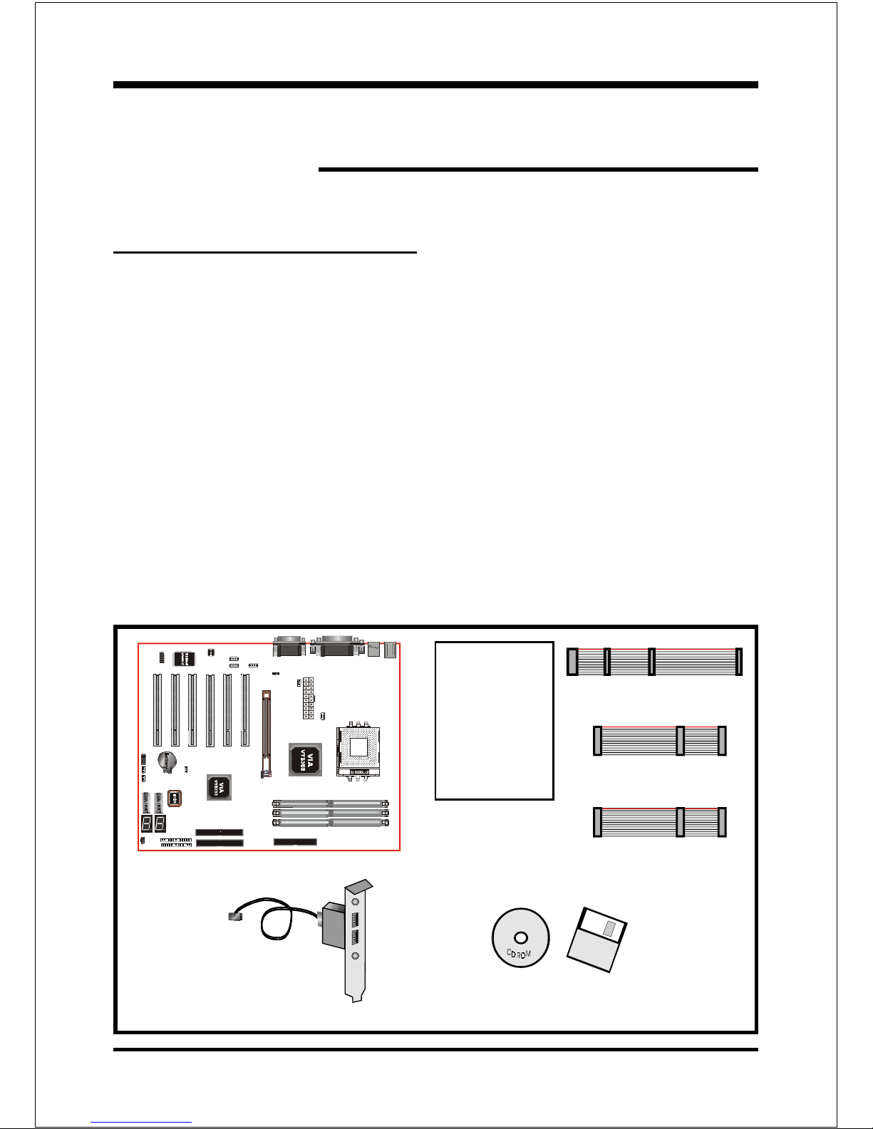
Components Checklist
99
99
9A. (1) Mainboard
99
99
9B. (1) Users manual
99
99
9C. (1) Floppy ribbon cable
99
99
9D. (1) ATA-66 100 Hard drive ribbon cable
99
99
9E. (1) USB Cable
99
99
9F. (1) Driver and utility
99
99
9G. (1) ATA-33 Hard drive ribbon cable
A
B
USERS
MANUAL
F
or
D
C
E
G

Introduction
Page 1-2
Overview
AMD DuronTM & AthlonTM Processors
The AMD AthlonTM is a seventh-generation micro architecture with an integrated
L2 cache, which is powerful enough to support the bandwidth requirements of a
large range of applications, hardware, graphics, and memory technologies. These
processors implement advanced design techniques such as:
Socket A (PGA 462)
200 266MHz system interface based on the Alpha EV6 bus protocol.
Three out-of-order, superscalar, pipelined Multimedia Units.
Three out-of-order, superscaler, pipelined Integer Units.
Fixed-sized internal instruction formats (MacroOPs).
72-entry Instruction Control Units.
AMD enhanced 3DNow! technology
L1 and L2 caches.
Dynamic branch prediction.
Socket A is the name for AMDs new socketed interface designed to support both
AMD DuronTM and AMD AthlonTM processors. This innovation is made possible
by integrating the L2 cache memory on chip with the processor. Socket A will
help enable smaller enclosures, and ultimately result in a wider variety of solu-
tions in the market.
The AMD DuronTM & AthlonTM processors in the Socket A format continue to
deliver the ultimate performance for cutting-edge applications. Both bring to
desktop systems running industry-standard x86 software superscalar RISC
performance. Being provided in the Socket A format they are the worlds most
powerful x86 processors. They easily deliver the highest integer, floating-point,
and 3D multimedia performance for applications running on x86 platforms
around.

Introduction
Page 1-3
The AMD DuronTM processor is derived from the AMD AthlonTM processor core.
It features full-speed, on-chip cache memory, a 200MHz front side system bus,
and enhanced 3DNow! technology. Although both processors are related, there
are key differences. The AMD AthlonTM processor is targeted at the performance
segment, and as such will have more cache memory and higher clock speeds.
Accelerated Graphics Port
(AGP or A.G.P.)
Typically, 3D graphics rendering requires a tremendous amount of memory, and
demands ever increasing throughput speed as well. As 3D products for the
personal computer become more and more popular, these demands will only
increase. This will cause a rise in costs for both end users and manufacturers.
Lowering these costs as well as improving performance is the primary motivation
behind AGP. By providing a massive increase in the bandwidth available between
the video card and the processor, it will assist in relieving some of these pressures
for quite sometime.
Ultra ATA/66/100
The board provides two channel (one channel is optional) Ultra ATA 66 100 Bus
Master IDE controller, that support Ultra ATA 66 100 protocols, perfect for such
demanding applications as real-time video, multimedia, and high performance
operating system. A new IDE cable is required for Ultra ATA 66 100. This cable
is an 80 conductor cable; however the connectors are, of course, backwards
compatible with ATA 33.
Hardware Monitoring
Hardware monitoring allows you to monitor various aspects of your systems
operations and status. The features include CPU temperature, voltage and RPM of
fan.

Introduction
Page 1-4
Mainboard Form-Factor
The board is designed with ATX form factor - the new industry standard of chassis.
ATX form factor is essentially a Baby-AT baseboard rotated 90 degrees within the
chassis enclosure and a new mounting configuration for the power supply. With
these changes the processor is relocated away from the expansion slots, allowing
them all to hold full length add-in cards. ATX defines a double height aperture to
the rear of the chassis which can be used to host a wide range of onboard I O.
Only the size and position of this aperture is defined, allowing PC manufacturers
to add new I O features (e.g.; TV input, TV output, joystick, modem, LAN, etc.) to
systems. This will help systems integrators differentiate their products in the
marketplace, and better meet your needs.
Smaller size promotes a smaller system size.
I O shield does not need to be retooled in an ATX 2.01 or later. The
mainboard should be used in an ATX 2.01 (or later) compliant case.
A smaller power supply can be used. High integration on mainboard
reduces the system costs.
PCI slots
Expandable I O
5 1/4"
Bay
3 1/2"
Bay
Figure 2: Summary of ATX chassis features
CPU
Single chassis
fan for system
ATX
Power
Supply
ATX power connec-
tor
Floppy IDE
connectors
AGP slot

Introduction
Page 1-5
Power-On/Off (Remote)
The board has a single 20-pin connector for ATX power supplies. For ATX power
supplies that support the Remote On/Off feature, this should be connected to the
systems front panel for system Power On Off button. The systems power On Off
button should be a momentary button that is normally open.
The board has been designed with Soft Off" functions. You can turn Off the
system from one of two sources: The first is the front panel Power On Off
button, and the other is the "Soft Off" function (coming from the M Bs onboard
circuit controller) that can be controlled by the operating system such
asWindows® 95 98 SE ME or Windows®2000.
Figure 4: Simple ATX Power ON/OFF Co troller
J 3
ATX
POWER SUPPLY
Case (chassis) Power
ON/OFF butto (J 3)
I/O Shield Connector
The board is equipped with an I O back panel. Please use the appropriate I O
shield (figure 3).
Figure 3: I/O back pa el layout MIC
parallel port Joystick/Midi port
USB port
COM1 COM2 Speaker
Li e_i
PS/2 Mouse
PS/2
KEYBOARD

Introduction
Page 1-6
Figure 5: System Block Diagram
System Block Diagram
PAC
PCI Bridge
and memory
controller
VT8366
266/200MHz
DDR SDRAM
133/100MHz
66MHz
4X
AMD
Socket A
Processors
VT8233
I/O Bridge
)+
'%
USB 0,1 USB 2,3 USB 4,5
Mouse
Keyboard
L C
W83697
Serial ort 1
Serial ort 2
L T ort
FDD
1,-
1,- HDD
(ATA-66/100)
V_Link
MA [0:13]
MDS [0:7]
MD [0:63]
Table of contents
Other EPOX Motherboard manuals


