Trotec VSP3041 User manual
TRT-BA-VSP3041-TC230915TTRT01-002-EN
VSP3041
EN
INSTRUCTIONS
VSP INSPECTION SYSTEM
2 EN
VSP inspection system VSP3041
Table of contents
Information on the use of this instructions..........................2
Safety .....................................................................................2
Information about the device................................................4
Transport and storage...........................................................8
Operation ...............................................................................9
Software...............................................................................15
Errors and faults..................................................................19
Maintenance and repair ......................................................19
Disposal ...............................................................................20
Information on the use of this instructions
Symbols
Warning of electrical voltage
This symbol indicates dangers to the life and health of
persons due to electrical voltage.
Warning
This signal word indicates a hazard with an average
risk level which, if not avoided, can result in serious
injury or death.
Caution
This signal word indicates a hazard with a low risk
level which, if not avoided, can result in minor or
moderate injury.
Note
This signal word indicates important information (e.g.
material damage), but does not indicate hazards.
Info
Information marked with this symbol helps you to carry
out your tasks quickly and safely.
Follow the manual
Information marked with this symbol indicates that the
instructions must be observed.
You can download the current version of the instructions and
the EUdeclaration of conformity via the following link:
VSP3041
https://hub.trotec.com/?id=43120
Safety
Read this manual carefully before starting or using the
device. Always store the manual in the immediate vicinity
of the device or its site of use.
Warning
Read all safety warnings and all instructions.
Failure to follow the warnings and instructions may
result in electric shock, fire and/or serious injury.
Save all warnings and instructions for future
reference.
• Do not use the device in potentially explosive rooms or
areas and do not install it there.
• Do not use the device in aggressive atmosphere.
• Do not use the device in atmospheres containing oil,
sulphur, chlorine or salt.
• Protect the device from permanent direct sunlight.
• Only use the device in de-energized facilities and objects.
For reasons of safety, de-energize all plant components
and objects prior to every inspection.
• Before using the measuring probes and camera heads,
de-energize any circuits located in walls.
• Before using the measuring probes and camera heads in
metal pipes inside a wall, have an authorised specialist
company carry out a check to ensure that the metal pipes
are not electrically charged.
• For reasons of safety, do not use the measuring probes
and camera heads for inspections in moving parts.
• Do not open the device.
• Do not remove any safety signs, stickers or labels from the
device. Keep all safety signs, stickers and labels in legible
condition.
• Observe the storage and operating conditions (see
Technical data).
Intended use
Only use the device for the visualization of objects.
To use the device for its intended use, only use accessories and
spare parts which have been approved by Trotec.
Any use other than the intended use is regarded as misuse.
EN 3
VSP inspection system VSP3041
Reasonably foreseeable misuse
Do not use the device:
• in potentially explosive atmospheres
• in live environments
• in unsuitable liquids, e.g. acids and alkalis
• on people or animals
Do not use the control unit with display underwater.
Any unauthorised modifications, alterations or structural
changes to the device are forbidden.
Personnel qualification
People who use this device must:
• take measures to protect themselves from direct contact
with live parts.
• have read and understood the instructions, especially the
Safety chapter.
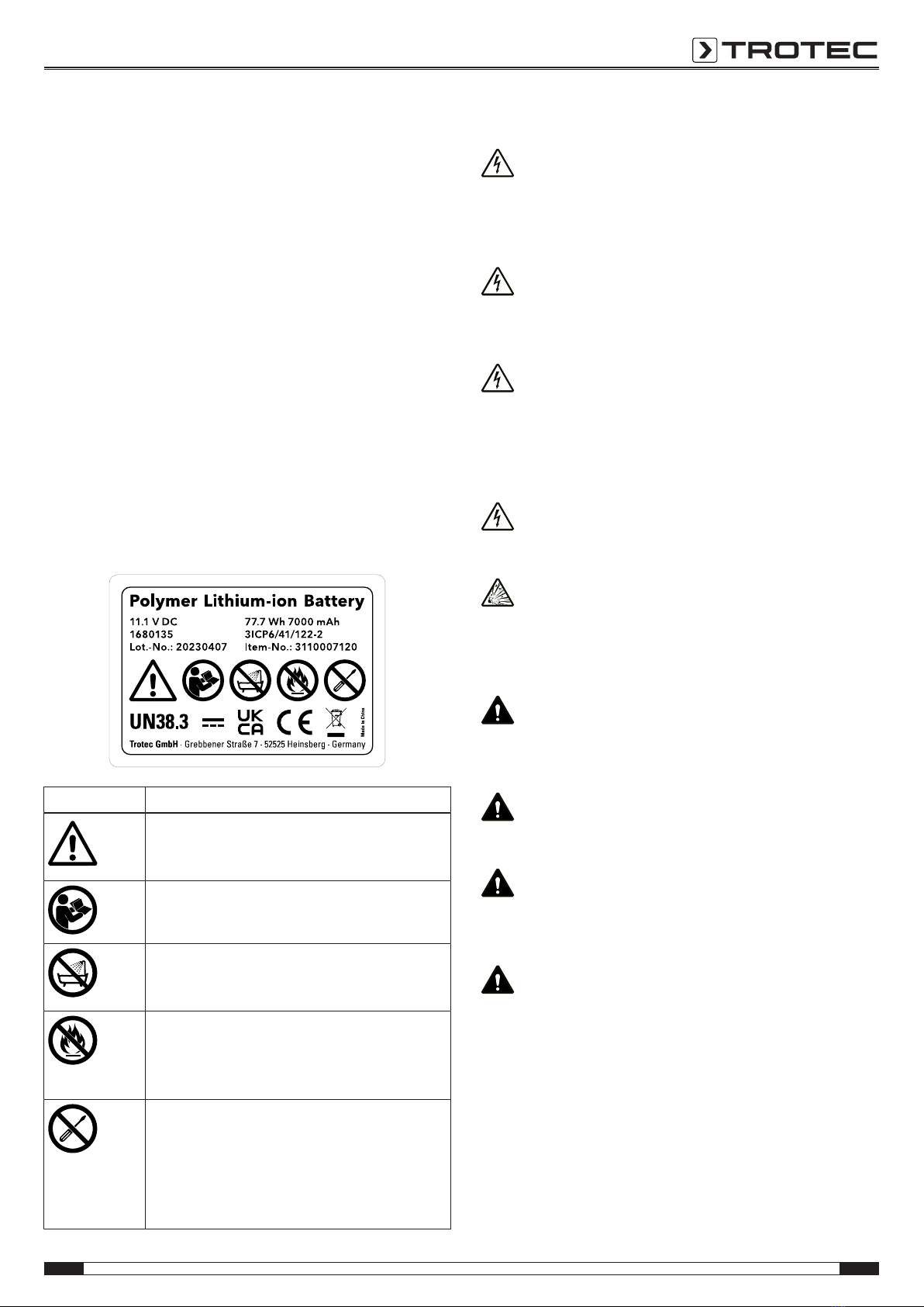
Safety signs and labels on the battery
Observe the label attached to the battery with the following
warnings:
Safety symbol Meaning
This symbol indicates that you must be aware
of the dangers that can occur when working
with the battery.
This symbol indicates that the operating manual
must be read before using the appliance.
Do not let the battery come into contact with
water! Avoid direct moisture. There is a risk of
explosion!
Do not expose the battery pack or tool to fire or
excessive temperature! Do not let the battery
come into contact with fire! Avoid direct solar
radiation. There is a risk of explosion!
This device may only be repaired and serviced
by the manufacturer. Any unauthorised
modifications, alterations or structural changes
to the device are forbidden.
Risk of injury due to electrical voltage. Damage
to the device may occur.
Residual risks
Warning of electrical voltage
Risk of death due to electric shock!
An electric shock can result in severe personal injury or
death! The device may only be used in accordance
with all safety instructions listed here.
Warning of electrical voltage
Electric shock due to contact with live parts! Do not
touch any live parts. Secure neighbouring live parts by
covering them or by switching them off.
Warning of electrical voltage
There is a risk of a short-circuit due to liquids
penetrating the housing!
Do not immerse the device and the accessories in
water. Make sure that no water or other liquids can
enter the housing.
Warning of electrical voltage
Work on the electrical components must only be
carried out by an authorised specialist company!
Warning of explosive substances
Do not expose the batteries to temperatures above
60°C! Do not let the batteries come into contact with
water or fire! Avoid direct sunlight and moisture. There
is a risk of explosion!
Warning
Risk of suffocation!
Do not leave the packaging lying around. Children may
use it as a dangerous toy.
Warning
The device is not a toy and does not belong in the
hands of children.
Warning
Dangers can occur at the device when it is used by
untrained people in an unprofessional or improper way!
Observe the personnel qualifications!
Caution
Lithium-ion batteries might catch fire in case of
overheating or damage. Ensure a sufficient distance to
heat sources, do not subject lithium-ion batteries to
direct sunlight and make sure not to damage the
casing. Do not overcharge lithium-ion batteries. If the
battery is not permanently installed in the device, only
use smart chargers that switch off automatically when
the battery is fully charged. Charge lithium-ion
batteries in due time before they are discharged
completely.
4 EN
VSP inspection system VSP3041
Caution
Keep a sufficient distance from heat sources.
Note
To prevent damages to the device, do not expose it to
extreme temperatures, extreme humidity or moisture.
Note
Do not use abrasive cleaners or solvents to clean the
device.
Information about the device
Device description
The device VSP3041 serves for inspecting concealed machine
components and poorly accessible or inaccessible hollows.
A high-resolution camera and a moveable camera head with an
adjustable, bright LED illumination are available for the display
and capturing/recording of images and videos. The supplied
camera head VSP‑H41M is connected to the push-cable drum
VSP‑R30 and modularly also to the mobile control unit
VSPControl. The supplied camera head can be exchanged for
other optional Trotec camera heads.
The camera's functions can be controlled via the mobile control
unit VSPControl. Using the provided snap-in system, the mobile
control unit can be affixed to the rear of the supplied push-cable
drum.
A digital metre counter with partial distance measurement
function is integrated in the push-cable drum.
The functions of the device VSP3041 can be controlled via the
integrated operator software of the VSPControl.
The recordings and measurements can be stored on an SD card
and transmitted via a USB interface.
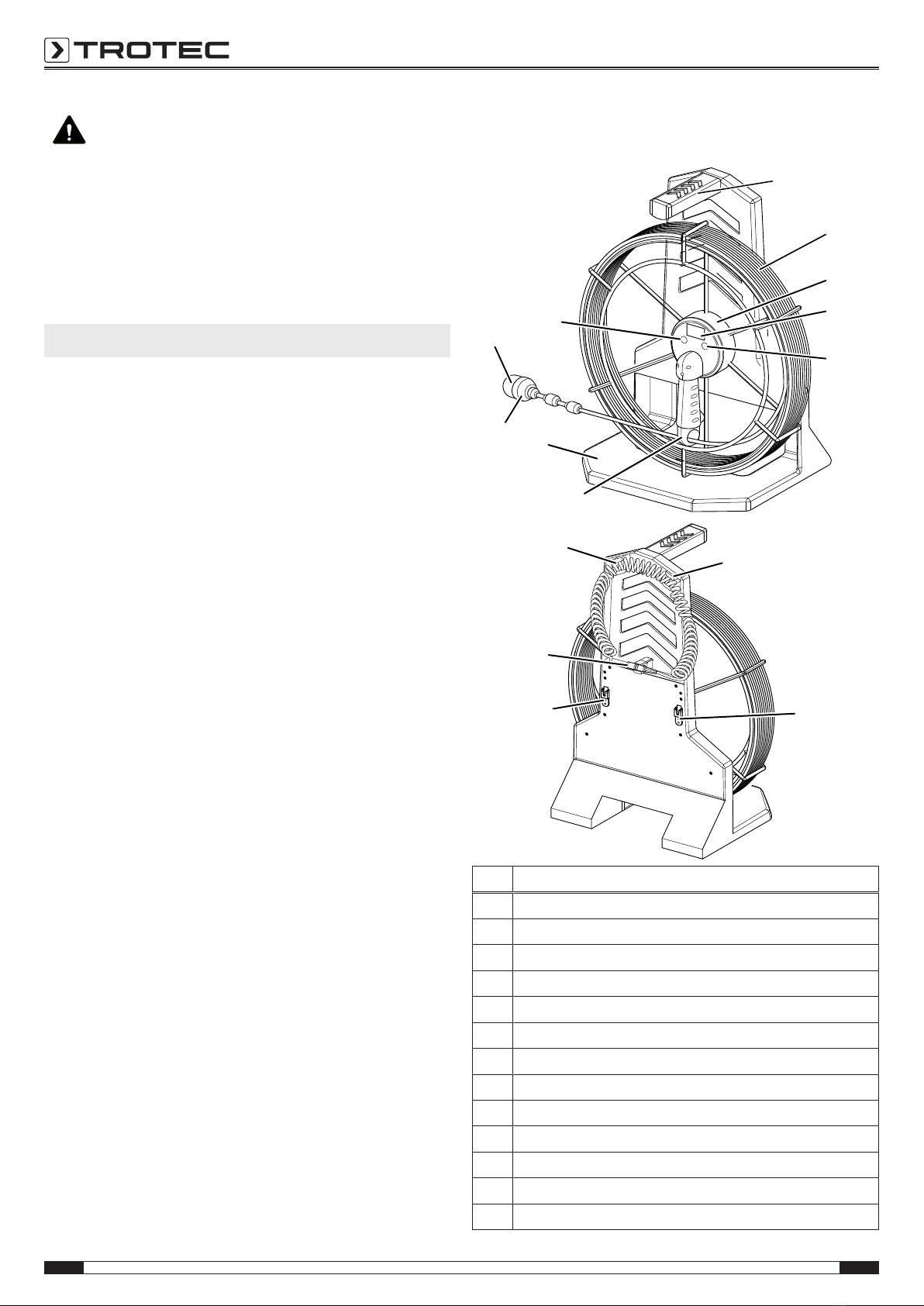
Device depiction
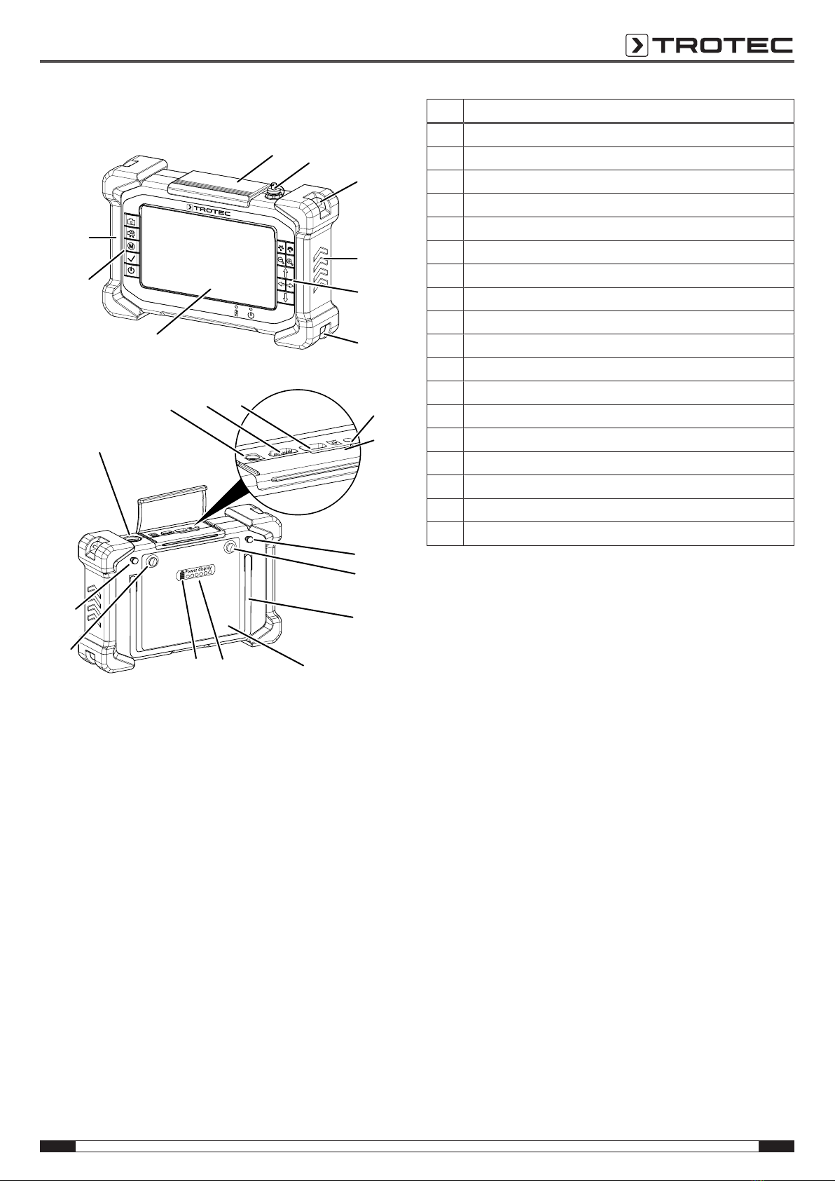
Push-cable drum and camera head
1
2
3
4
5
6
7
8
9
10
11
12
12
13
11
No. Designation
1Carrying handle push-cable drum
2Push cable
3Un-/reeling aid
4Digital metre counter
5Section button
6Coiled cord brake
7Foot
8Exchangeable camera head
9Plastic protective cap
10 Clear button
11 Coiled cord holder
12 Snap-in system for attaching the VSPControl
13 Multi-connector for the VSPControl
EN 5
VSP inspection system VSP3041
Control unit VSPControl
15
16
17
18
16
19
44
18
14
29 31 20
21
22
23
24
2526
23
22
28
30
27
No. Designation
14 Protective flap
15 Sealing cap multi-connector socket
16 Wrist strap holder
17 Rubber protectors
18 Control panel
19 Display
20 Audio connection
21 SD card slot
22 Standoff for snap-in attachment to the push-cable drum
23 Battery attachment screw
24 Fold-out stand
25 Battery
26 Battery level indication
27 Battery test button
28 Multi-connector socket with protective cap
29 Power adapter connection
30 HDMIport
31 USBconnection
6 EN
VSP inspection system VSP3041
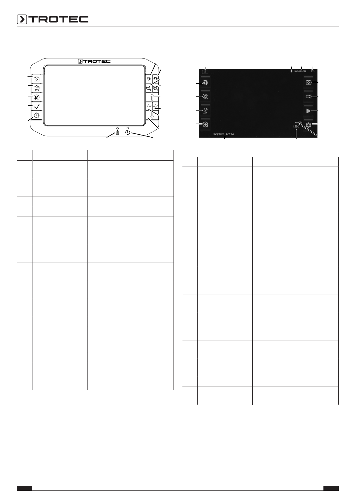
Operating elements
32
34
35
36
37
38
39
4041
42
43
44
45
46
33
No. Designation Meaning
32 Minus brightness
button
For reducing the illumination
intensity at the camera head
33 Plus brightness
button
For increasing the illumination
intensity at the camera head
34 Minus focus button For focussing on close objects
35 Plus focus button For focussing on distant objects
36 Arrow button up For moving the camera head up
37 Right arrow button For moving the camera head to
the right
38 Left arrow button For moving the camera head to
the left
39 Down arrow button For moving the camera head
down
40 Operation indicator Is illuminated in red when the
device is switched on.
41 Charging indicator Is illuminated in red when the
device is charging.
42 Power button Switching the device on and off
43 Confirm button For confirming the selection/
opening the browser for
recordings
44 Menubutton For opening/ closing the menu
45 Video button For starting/ stopping a video
recording
46 Photo button For taking a photo
Display
47
48
49
50
51
5253
54
55
56
57
5958 60 61
No. Designation Meaning
47 Photo display button For taking a photo
48 Video display button For starting/ stopping a video
recording
49 Play display button Opens the browser for photo and
video recordings
50 Settings display
button
Opens the menu
51 Metre counter
indication
Indicates metre reading
52 LEDindication Indicates the number of activated
LEDs (0– 12)
53 Time stamp
indication
Date and time printed on
recordings
54 Zoom display button Zooming in
55 Dual Vision display
button
Switch between camera views
(depending on the probe version)
56 Grid display button Show/hide grid
57 Negative display
button
Invert display colours
58 Rotation indication Indicates whether the display has
been rotated
59 Memory card
indication
Indicates whether the memory
card is activated
60 Date indication Indicates the current date
61 Battery status
indication
Indicates the charge status of the
battery
EN 7
VSP inspection system VSP3041
Technical data
Parameter Value
Control unit VSPControl
Article number 3.110.007.110
Display brightness
control
manually adjustable
LCD display 7inch TFT LCD (1280 x 720px)
Type of protection IP67
Memory slot for removable SDcard (max. 64GB)
File formats image format JPEG (1024x768), video
format AVI
(640x480[4:3]or800x480[16:9])
Power supply 11.1V lithium polymer battery pack
(7,000mAh, charging time 8h), power
adapter
Interfaces USB, SDcard slot, HDMI, multi-
connector socket for push-cable
camera, borescope and videoscope,
(analogue video NTSC/PAL optional)
Dimensions 257x 171x 64mm
Weight 1.74kg
Physical
characteristics
rubberized operator keypad, lateral
rubber protectors, wrist straps, fold-out
stand, integrated battery capacity
indication
Control software
Operator guidance simple interactive menu control
Available menu
languages
German, English, French, Italian, Dutch,
Danish, Finnish, Portuguese, Russian,
Spanish, Chinese, Korean, Japanese,
Turkish
Software functions system settings, video settings, memory
functions
Parameter Value
Push-cable drum VSP‑R30
Article number 3.110.007.115
Type Fibreglass-reinforced
Push cable
Dimensions length 30m, ø 5.4mm
90° bend flexibility lines ≥135mm
Protection type of the
camera head
connection
IP67
Drum
Dimensions 515x 405x 200mm
Weight 6.5kg
Parameter Value
Camera head VSP‑H41M
Article number 3.110.007.130
Diameter ø 41mm
Length 60 mm
Resolution 1,000,000pixels
Focus manual
Illumination 12 LEDs
DOF 15mmto∞
Field of vision >75°
Pivoting radius 180°
Rotation 360°
Type of protection IP67
Watertightness to a depth of 1m
Material Stainless steel probe with plastic dome
Parameter Value
Transmitter VSP3041
Transmission
frequency
512Hz
Frequency
modulation
FM
Max. transmission
power
45mW
Range 5m*
Dimensions length 66.8mm, ø 21 mm
*The range may vary depending on the receiver and the surface/material to be
penetrated.
8 EN
VSP inspection system VSP3041
Scope of delivery
• 1x VSPControl with Li-ion battery
• 1x Push-cable drum VSP‑R30
• 1x Camera head VSP‑H41M
• 1 x Transport case
• 1 x SD card
• 1x USBcable (typeA-A, for the connection of a compatible
external monitor)
• 1 x HDMIcable
• 5x Spare protective cap for camera head VSP‑H41M
• 1 x LCD cleaning cloth
• 1x Plug-on anti-glare shield
• 1x Tool for disconnecting the camera heads
• 1 x Charger
• 1x Manual
Further information on spare parts and accessories is available
via the following link:
https://hub.trotec.com/?id=43120
Transport and storage
Note
If you store or transport the device improperly, the
device may be damaged.
Note the information regarding transport and storage of
the device.
Transport
For transporting the device, use the transport case included in
the scope of delivery in order to protect the device from external
influences.
The supplied Li-ion batteries are subjects to the requirements of
dangerous goods legislation.
Observe the following when transporting or shipping Li-ion
batteries:
• The user may transport the batteries by road without any
additional requirements.
• If transport is carried out by third parties (e.g. air transport
or forwarding company), special requirements as to
packaging and labelling must be observed. This includes
consulting a dangerous goods specialist when preparing
the package.
– Only ship batteries if their housing is undamaged.
– Mask open terminals with tape and pack the battery in
a way that it cannot move inside the packaging.
– Please also observe any other national regulations.
Storage
When the device is not being used, observe the following
storage conditions:
• dry and protected from frost and heat
• protected from dust and direct sunlight
• For storing the device, use the transport case included in
the scope of delivery in order to protect the device from
external influences.
• the storage temperature complies with the values specified
in the Technical data
• Battery/Batteries removed during prolonged storage
EN 9
VSP inspection system VSP3041
Operation
Inserting the battery into the control unit VSPControl/
exchanging the battery
Note
Make sure that the surface of the device is dry and the
device is switched off.
1. Loosen the two attachment screws(23) at the rear of the
rechargeable battery(25) without removing them.
ðThe battery can now be removed.
2. When inserting the battery, first place the locating tabs at
the bottom of the battery into the designated openings at
the rear of the device.
3. Now slightly press the top of the battery down and tighten
the two attachment screws(23) at the rear of the battery.
ðThe battery is inserted in the device
Inserting the SD card
1. Lift off the protective flap(14) at the top of the VSPControl.
2. Insert the SDcard in the SDcard slot(21).
3. Slightly press down the SDcard until it engages.
4. Close the protective flap(14) again.
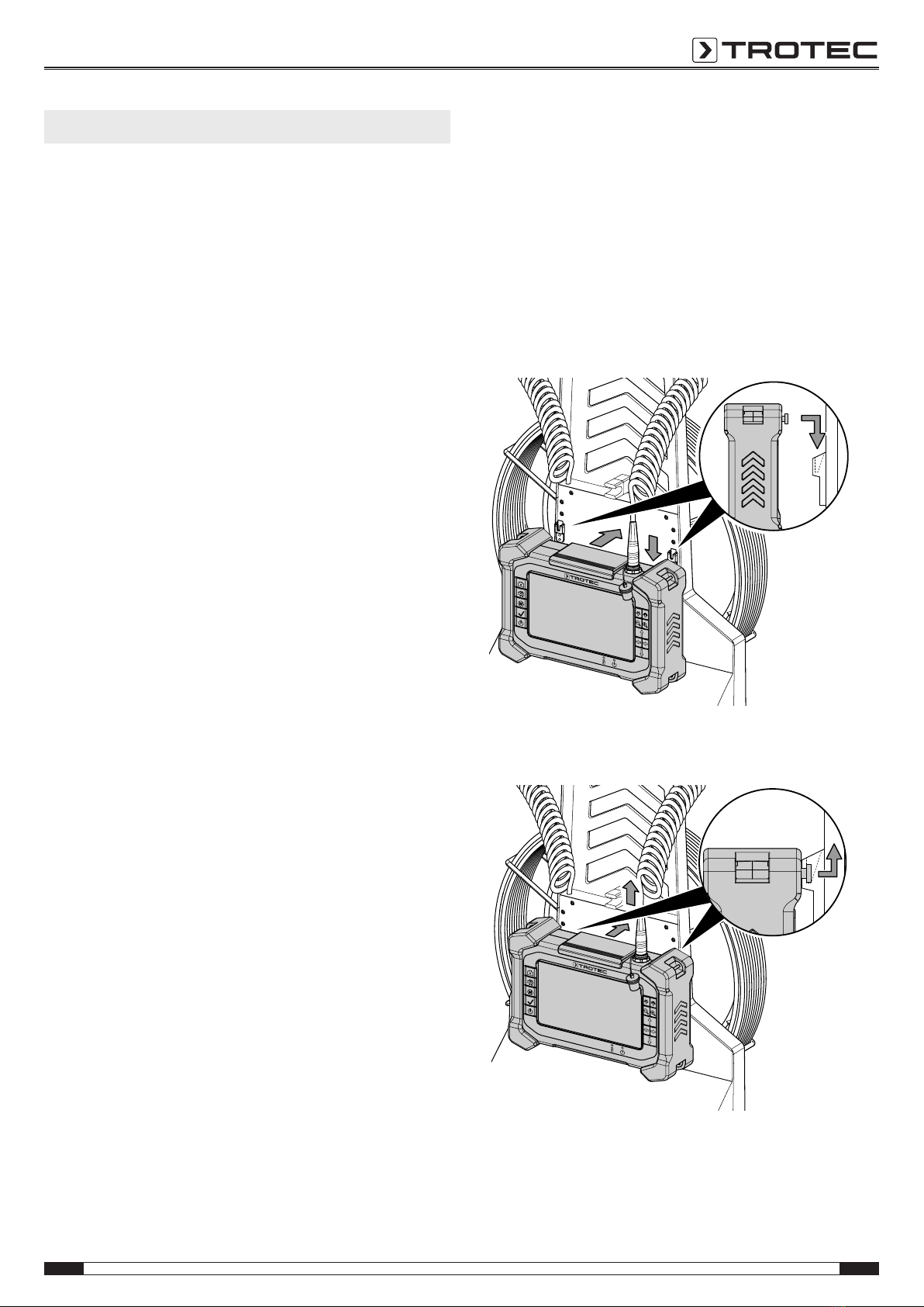
Connecting the control unit VSPControl to the push-cable
drum VSP‑R30 and attaching/ removing it
Please proceed as follows if you want to connect the control unit
VSPControl to the supplied push-cable drum VSP‑R30 and
attach or remove it:
1. Pull out the sealing cap for the multi-connector socket (15)
on the top of the VSPControl.
ðThe sealing cap is attached to a wire on the control unit.
Make sure that the plug is located on the display side
and does not dangle at the rear of the VSPControl.
2. Plug the multi-connector(13) at the rear of the push-cable
drum into the multi-connector socket(28) on top of the
VSPControl so that it fits exactly.
ðMake sure that the red markings on the plug and socket
are aligned and that the multi-connector engages firmly.
3. Lift the control unit VSPControl onto the snap-in
system(12) at the rear of the push-cable drum VSP‑R30.
First press the control unit against the push-cable drum's
rear panel, then downwards. The two standoffs for snap-in
attachment(22) at the rear of the control unit VSPControl
must engage with the two guide rails of the snap-in
system(12).
4. In order to detach the VSPControl, first press it against the
push-cable drum, then upwards.
10 EN
VSP inspection system VSP3041
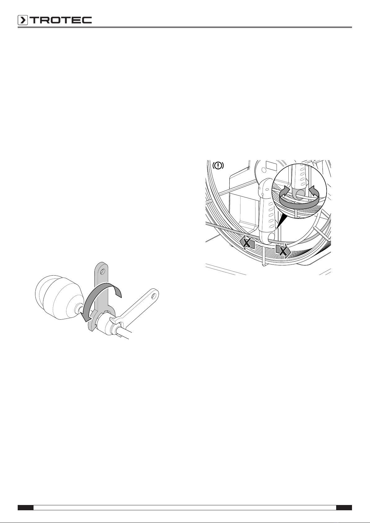
Connecting the camera head to the push-cable drum
You can connect the supplied camera head (or one of the
optional camera heads from Trotec) to the end of the push-
cable drum VSP‑R30. Please proceed as follows to connect the
supplied camera head VSP‑H41M to the push-cable drum:
Note
Only use the tool included in the scope of delivery to
connect a camera head to the push-cable drum.
1. Unless already carried out upon delivery, first guide the
push cable without camera head through the hole in the
coiled cord brake(6).
2. Unreel the push cable(2) a little for better access to the
end of the push-cable drum.
3. Lock the push cable with the brake as described in the
section "Preventing the push cable from unreeling using
the brake" to prevent further unreeling.
4. Manually screw the camera head's threaded connector
clockwise onto the threaded connection at the end of the
push cable.
5. To fasten the connection, apply the supplied wrench just
beneath the threaded connection of the push cable as
depicted. Make sure that the wrench engages with the
existing grooves so it cannot slip.
6. Apply the other supplied wrench to the threaded
connection beneath the camera head and make sure that
its teeth engage with the grooves under the threaded
connection.
ðTurn the wrench until the camera head is fixed in place.
7. Also use the supplied wrenches as described to disconnect
and possibly replace the camera head from the push-cable
drum.
Preventing the push cable from unreeling using the brake
Note
The push cable of the VSP-R30 push-cable drum is
tensioned and can unwind unexpectedly. Use the
coiled cord brake(6) if you do not want to unwind the
push cable.
You can use the integrated brake(6) to prevent the push cable
from unwinding unintentionally. To do so, please proceed as
follows:
1. Turn the coiled cord brake(6) inwards so that the coiled
cord can no longer be rolled off.
2. To release the coiled cord brake(6) turn it back into its
initial position.
Using plastic protective caps
Note
In order to prevent damaging of the device, never use
the camera head VSP‑H41M without one of the impact-
proof and break-resistant plastic protective caps from
the scope of delivery.
Unless already preassembled you should protect the camera
head by mounting one of the supplied plastic protective caps as
follows before every application:
1. Check the threading of the camera head for dirt and clean
it if necessary.
2. Attach the plastic protective cap(9) to the camera head(8)
and make sure that the threading does not get wedged.
Screw the plastic protective cap down by hand.
ðMake sure that neither dirt nor moisture can enter the
movable camera unit.
3. If the mounted plastic protective cap was affected too
much by using the device resulting in too many scratches,
replace it with a new one.
Other manuals for VSP3041
1
Table of contents
Other Trotec Measuring Instrument manuals


