From the Nernst equation, the theoretical
response of a sodium ion-selective electrode to
a ten-fold change in concentration at 25 ºC is
59.16 mV. This is referred to as the electrode
slope(s). Most electrodes, however, do not
exhibit a theoretical slope. Therefore, the
instrument is calibrated to determine its actual
value. Two standards are used to provide
information necessary for the microprocessor to
compute the actual slope and E0for use during
sample analysis.
In order to eliminate interference from hydrogen
ions which can become significant when
measuring low levels of sodium, the Model 1811EL
Monitor adjusts sample pH to above 11. This pH
adjustment is accomplished by the patented
passive diffusion process wherein the sample
passes through a tubing coil present in the
reagent bottle containing aqueous amine solution
which diffuses through the tube wall and
redissolves, raising sample pH to about 11.
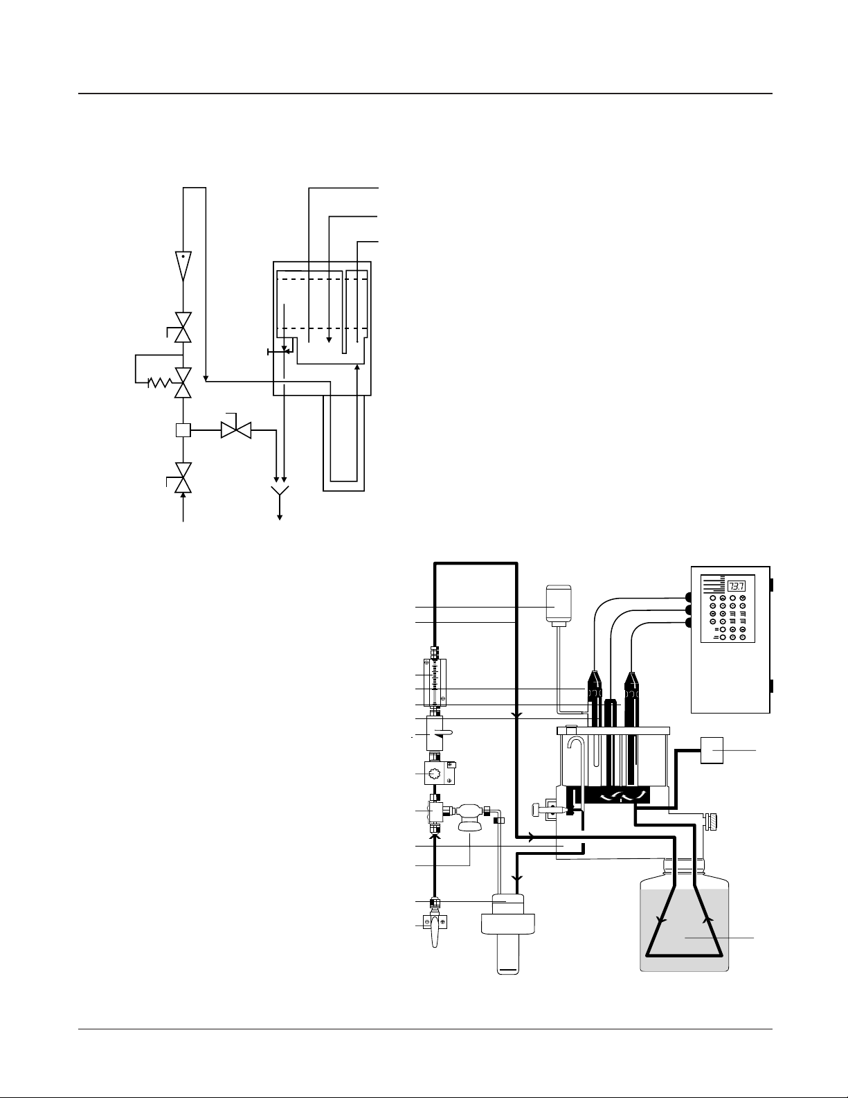
Flow of sample into reservoir of flow cell is set by
a combination of pressure regulator and flow
restrictor tube. The pressure regulator is adjusted
to give a nominal flow of 40 mL/min. The diverter
valve on the flow cell is pulled out during normal
operation, which maintains a sample reservoir
volume of approximately 20 mL. Therefore, this
system’s fast response time is a result of both
sample volume and flow rate. The air for mixing
the sample is recirculated to eliminate potential
sodium contamination from airborne salt.
Principles of Calibration
Double-Known Addition (DKA)
Numbers refer to Figure 3.
Calibration procedures for an analytical instrument
are important and must be performed carefully.
The patented calibration procedure used in the
Model 1811EL is a variation on Double Known
Addition (DKA). This method has distinct
advantages when compared with conventional
methods of calibration. It is fast, easy, accurate
and uses a readily available pipet for calibration.
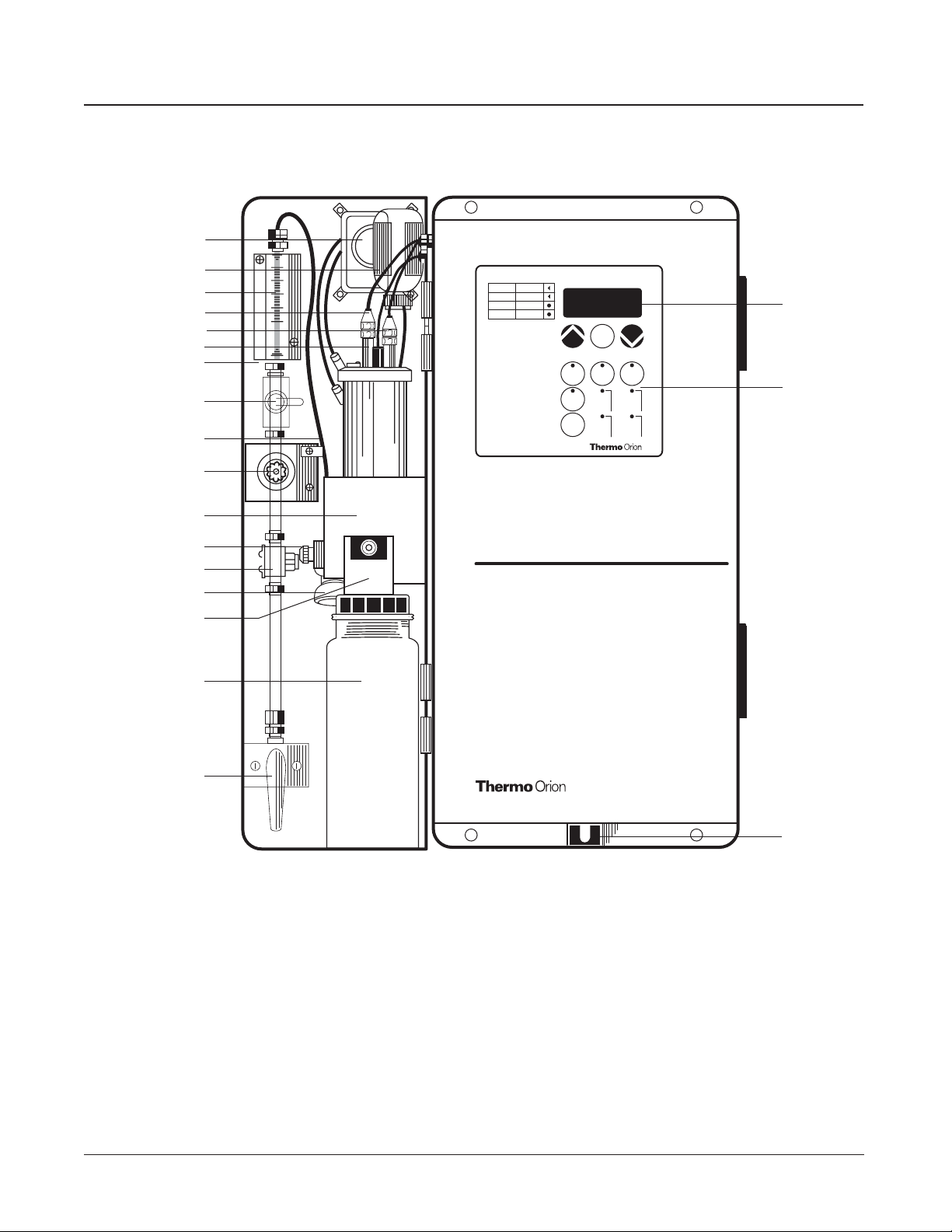
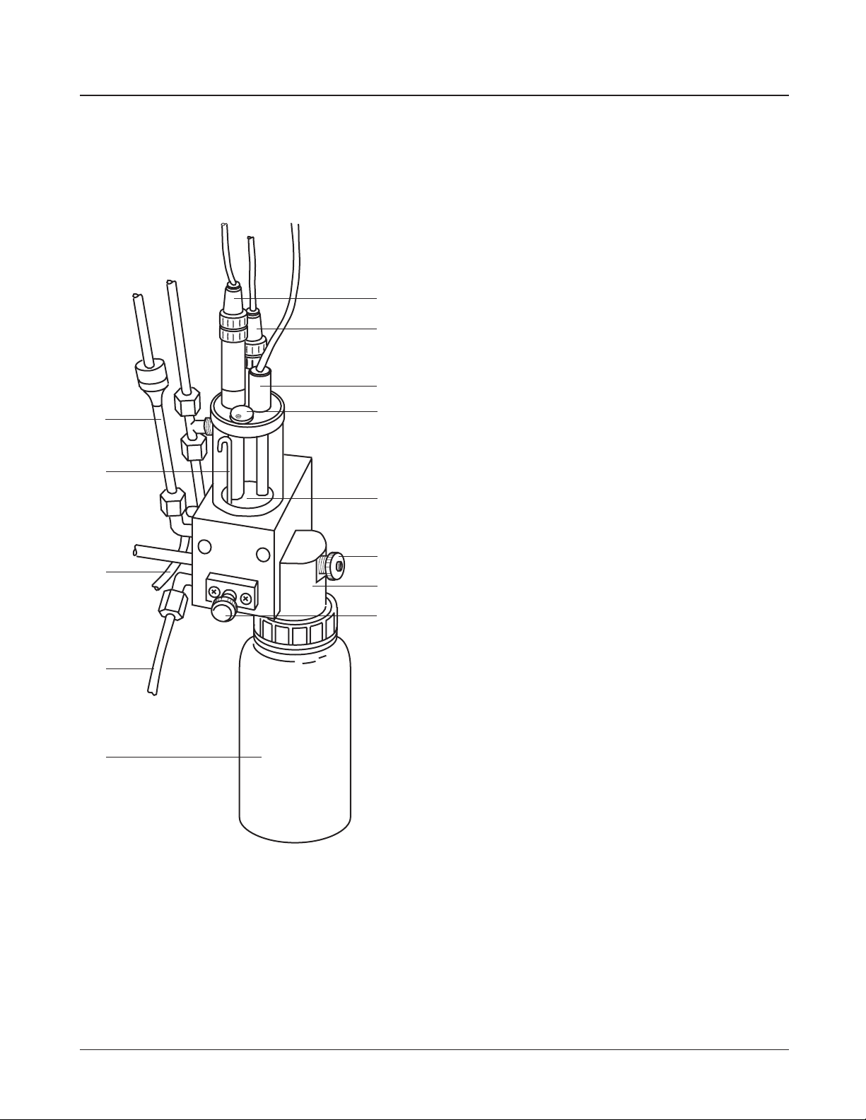
The sample reservoir, as shown in Figure 1, has
two sample volumes; a normal operation volume
(about 20 mL) and a calibration volume (about
100mL). The lower volume results in fast system
response while on-line, and the higher volume
ensures accuracy in calibration. The sample
diverter valve, 12, is pushed in to fill the sample
reservoir to 100 mL volume prior to calibration.
At this point the actual concentration in the
sample is unknown but the instrument measures
the potential (Es) and stores this value in the
microprocessor. A known amount of Standard
Solution 1 is added to the sample reservoir which
increases the concentration (Cs) with a
corresponding known amount (dC1). The new
potential (E1) is measured and stored
automatically, when stability is reached. Standard
2, preferably 10 times more concentrated than
Standard 1, is added which again increases the
concentration (dC2) in the sample reservoir. Again
the new potential (E2) is measured and stored
when stable. Now, we have the following three
unknowns:
Es=E
0+ S log (Cs/Ciso)
E1=E
0+ S log [(Cs+ dC1)/Ciso]
E2=E
0+ S log [(Cs+ dC1+ dC2)/Ciso]
Es, E1, E2have been determined during the
calibration procedure. The microprocessor solves
these three equations giving the values of S and
E0. This data is stored for use during on-line
monitoring to convert the measured potential in
the sample into concentration values either in ppm
or ppb.
2
Model 1811EL Low-Level Sodium Monitor