Spectris PARTICLE MEASURING SYSTEM HSLIS e-Series User manual

HSLIS e-Series
Particle Counter
P/N 1000003538
OPERATIONS MANUAL
Without measurement there is no control

HEADQUARTERS
5475 Airport Blvd
Boulder, Colorado 80301 USA
T: +1 303 443 7100
Instrument Service & Support
T: +1 800 557 6363
Customer Response Center
T: +1 877 475 3317
E: Info@pmeasuring.com
GLOBAL OFFICES
AUSTRIA
T: +43 1 71 728 285
E: pmsaustria@pmeasuring.com
BENELUX
T: +32 10 23 71 56
E: pmsbelgium@pmeasuring.com
BRAZIL
T: +55 11 5188 8227
E: pmsbrazil@pmeasuring.com
CHINA
T: +86 21 6113 3600
E: pmschina@pmeasuring.com
FRANCE
T: +33 (0)1 60 10 32 96
E: pmsfranc[email protected]om
GERMANY
T: +49 6151 6671 632
E: pmsgermany@pmeasuring.com
ITALY
T: +39 06 9053 0130
E: pmssrl@pmeasuring.com
JAPAN
T: +81 44 589 3498
E: pmsjapan@pmeasuring.com
KOREA
T: +82 31 286 5790
E: pmskor[email protected]om
MEXICO
T: +52 55 2271 5106
E: pmsmexic[email protected]
NORDIC
T: +45 707 028 55
E: pmsnordic@pmeasuring.com
PUERTO RICO
T: +1 787 718 9096
E: pmspuertoric[email protected]om
SINGAPORE
T: +65 6496 0330
E: pmssingapore@pmeasuring.com
SWITZERLAND
T: +41 71 987 01 01
E: pmsswitzerland@pmeasuring.com
TAIWAN
T: +886-3-5525300 Ext: 301
E: pmst[email protected]om
HSLIS e-Series Particle Counter
Operations Manual
P/N 1000003538 Rev V

ii HSLIS e-Series Operations Manual
HSLIS e-Series Particle Counter Operations Manual
P/N 1000003538 Rev V
© 2022 by Particle Measuring Systems, Inc.
All rights reserved.
Delrin®, Kalrez®, Teflon®, and Viton® are registered trademarks of Dupont Polymers, Inc.
Flaretek® is a registered trademark of Fluroware, Inc.
HyperTerminal® is a registered trademark of Hilgraeve, Inc.
KEL-F® is a registered trademark of the Minnesota Mining and Manufacturing Company.
Slo-Blo® is a registered trademark of Littelfuse, Inc.
Windows® is a registered trademark of the Microsoft Corporation.
All trademarks appearing in this manual are the property of their respective owners.
This confidential document contains proprietary information, which is protected by
copyright. All rights are reserved. No part of this document may be reproduced,
distributed, or transmitted in any form without the prior written consent of Particle
Measuring Systems. The information contained in this document is subject to change
without notice.
Quality Statement
The Quality Policy of Particle Measuring Systems is to strive to meet or exceed the
needs and expectations of our customers, and to align the activities of all employees
with the common focus of customer satisfaction through continuous improvement in
the quality of our products and services.
Environmental Information
This equipment must be properly disposed of at end-of-life by means of an
authorized waste management system. Contact our Customer Response Center at
(877) 475-3317 or (303) 443-7100 (International Telephone +1 3034437100) for
dismantling and disposal information.
DO NOT REPRODUCE OR DISTRIBUTE CONFIDENTIAL DOCUMENT

HSLIS e-Series Operations Manual iii
Manual Conventions
It is important that you observe cautions and warnings while performing the
procedures described in this manual. Caution and warning labels are located on and
inside the instrument to alert you to potentially hazardous conditions. Please
familiarize yourself with this information.
WARNING
A warning in the text is used to notify the user of the potential for bodily injury or
death.
CAUTION
A caution in the text is used to highlight an item that if not done, or incorrectly done,
could damage the instrument and/or any materials or devices affected by the
instrument.
– — NOTICE — –
A notice in the text is an instructional communication regarding requirements or
policies issued by Particle Measuring Systems.
NOTE: A note in the text is used to highlight an item that is of operational importance
to the user.
iv HSLIS e-Series Operations Manual
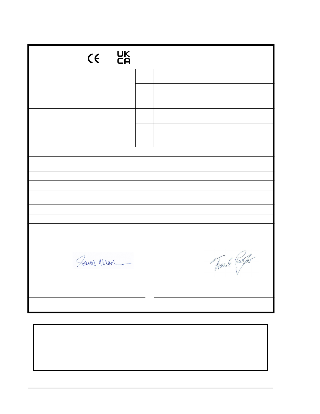
and Declaration of Conformity
Application of Council Directive(s): CE 2014/30/EU, 2014/53/EU, 2014/35/EU, RoHS 2011/65/EU,
2015/863
UKCA Electromagnetic Compatibility Regulations 2016,
Electrical Equipment (Safety) Regulations 2016
The Restriction of the Use of Certain Hazardous Substances in
Electrical and Electronic Equipment Regulations 2012
Standard(s) to which Conformity is Declared: EMC EN 61326-1:2013
S.I. 2016 No. 1091
Safety EN 61010-1: 2010, 3rd, Ed.
S.I. 2016 No. 1101
RoHS BS EN 63000:2018
Manufacturer’s Name: Particle Measuring Systems, Inc.
Manufacturer’s Address: 5475 Airport Boulevard
Boulder, CO 80301 USA
Manufacturer’s Telephone/FAX: + 1 3034437100 / + 1 3034496870
Distributor’s Name: Particle Measuring Systems, S.R.L.
Distributor’s Address Via di Grotte Portella 34
00044 Frascati (Roma) ITALY
Distributor’s Telephone/FAX: + 39 06 90530130 / + 39 06 9051315
Type of Equipment: Particle Monitoring
Model No: HSLIS e-Series
I, the undersigned, hereby declare that the equipment specified above conforms to the above Directive(s) and Standard(s).
Signature: Signature:
Full Name: Scott MacLaughlin Full Name: Frank Panofen
Position: Director of Engineering Position: Marketing Manager, Life Sciences
Place: Boulder Date: June 14, 2022 Place: Rome Date: June 14, 2022
CAUTION
All I/O cables and accessories must meet current factory specifications in order for this unit to
remain in compliance with CE marking requirements. Consult the factory for details.
If the equipment is used in a manner not specified by the manufacturer, the protection provided
by the equipment may be impaired.
HSLIS e-Series Operations Manual v
Hazardous Material Leakage Procedure
WARNING If the hazardous contaminant is an
1. Test with litmus paper and continue neutralization until neutral pH (7) is
achieved.
2. If allowed by local environmental regulations, flush the neutralized
contaminant down the drain (not a storm sewer) with a volume of clean water
at least 100 times the volume of the neutralized contaminant.
3. If local regulations do not allow draining of the neutralized contaminant,
contain it appropriately and have it disposed of by a hazardous waste disposal
firm.
4. To prevent corrosion, internally-contaminated instruments must be air dried
following clean-up and before reassembly.
5. Chlorinated solvents, organic solvents, or other chemicals should be contained
for recycling or disposal by a hazardous waste disposal firm.
6. Using clean water, flush the instrument until it is free of chemicals.
Be sure to air dry the instrument before reassembly, packing and shipping. Fill the
liquid particle counters’ sample cells with a Particle Measuring Systems-approved
cleaning solution and then seal the particle counter’s inlet and outlet ports.
– — NOTICE: — –
Do not ship contaminated instruments to Particle Measuring Systems for repair
without first draining and flushing the instrument with large amounts of water!
– — NOTICE: — –
Particle Measuring Systems cannot service instruments that have been
contaminated with radioactive materials.

vi HSLIS e-Series Operations Manual
This page is intentionally left blank.

HSLIS e-Series Operations Manual vii
Table of Contents
Quality Statement - - - - - - - - - - - - - - - - - - - - - - - - - - - - - - - - - - - - - - - - - ii
Environmental Information - - - - - - - - - - - - - - - - - - - - - - - - - - - - - - - - - ii
Manual Conventions - - - - - - - - - - - - - - - - - - - - - - - - - - - - - - - - - - - - - - iii
List of Figures - - - - - - - - - - - - - - - - - - - - - - - - - - - - - - - - - - - - - - - - - - - - - - - - - - - - - - ix
List of Tables - - - - - - - - - - - - - - - - - - - - - - - - - - - - - - - - - - - - - - - - - - - - - - - - - - - - - - - xi
Chapter 1: Introduction - - - - - - - - - - - - - - - - - - - - - - - - - - - - - - - - - - - - - - - - - - - - - 1-1
Specifications- - - - - - - - - - - - - - - - - - - - - - - - - - - - - - - - - - - - - - - - - - - - - - 1-3
Chapter 2: Unpacking & Installation - - - - - - - - - - - - - - - - - - - - - - - - - - - - - - - - - - - 2-1
Unpacking - - - - - - - - - - - - - - - - - - - - - - - - - - - - - - - - - - - - - - - - - - - - - - - - 2-1
Recycling - - - - - - - - - - - - - - - - - - - - - - - - - - - - - - - - - - - - - - - - - - - - - - - - - 2-2
Installation- - - - - - - - - - - - - - - - - - - - - - - - - - - - - - - - - - - - - - - - - - - - - - - - 2-3
Moving the Instrument to the Work Area- - - - - - - - - - - - - - - - - - - - - - 2-3
Installing the Plumbing Connections - - - - - - - - - - - - - - - - - - - - - - - - 2-3
Connecting the Cables - - - - - - - - - - - - - - - - - - - - - - - - - - - - - - - - - - - - 2-4
Status LED - - - - - - - - - - - - - - - - - - - - - - - - - - - - - - - - - - - - - - - - - - - - - - - - 2-4
Status LED Use with Facility Net - - - - - - - - - - - - - - - - - - - - - - - - - - - - 2-4
Status LED Use Without Facility Net - - - - - - - - - - - - - - - - - - - - - - - - - 2-4
Activity LED - - - - - - - - - - - - - - - - - - - - - - - - - - - - - - - - - - - - - - - - - - - - - - - 2-4
Chapter 3: Set Up for Ethernet Communications- - - - - - - - - - - - - - - - - - - - - - - - - - 3-1
Connecting a Computer to the Particle Counter- - - - - - - - - - - - - - - - - - - 3-2
Setting Up a Terminal Emulation Session - - - - - - - - - - - - - - - - - - - - - - - - 3-2
Running a Status Check - - - - - - - - - - - - - - - - - - - - - - - - - - - - - - - - - - - - - - 3-5
Setting IP Addresses - - - - - - - - - - - - - - - - - - - - - - - - - - - - - - - - - - - - - - - - 3-6
Connecting the Ethernet Cable - - - - - - - - - - - - - - - - - - - - - - - - - - - - - - - - 3-8
Straight Through Ethernet Cable Pinouts - - - - - - - - - - - - - - - - - - - - - 3-9
Crossover Ethernet Cable Pinouts - - - - - - - - - - - - - - - - - - - - - - - - - - - 3-10
Chapter 4: Operations- - - - - - - - - - - - - - - - - - - - - - - - - - - - - - - - - - - - - - - - - - - - - - - 4-1
Setting Sample Parameters- - - - - - - - - - - - - - - - - - - - - - - - - - - - - - - - - - - 4-1
Calculating the Sample Interval - - - - - - - - - - - - - - - - - - - - - - - - - - - - - - - 4-2
Setting the Sample Interval - - - - - - - - - - - - - - - - - - - - - - - - - - - - - - - - - - - 4-2
Starting the HyperTerminal Program - - - - - - - - - - - - - - - - - - - - - - - - 4-3
Entering the Sample Interval - - - - - - - - - - - - - - - - - - - - - - - - - - - - - - - 4-3
Using Facility Net with the HSLIS e-Series Particle Counter - - - - - - - - - - 4-4

viii HSLIS e-Series Operations Manual
Chapter 5: Operating with the 4-20 mA Outputs- - - - - - - - - - - - - - - - - - - - - - - - - - 5-1
Connecting a Computer to the Particle Counter- - - - - - - - - - - - - - - - - - - 5-2
Setting up a Terminal Emulation Session (with 4-20 mA Outputs)- - - - - 5-2
Setting 4-20 mA Parameters - - - - - - - - - - - - - - - - - - - - - - - - - - - - - - - - - - 5-3
Connecting HSLIS e-Series Particle Counter to SCADA or PLC - - - - - - - - 5-5
Factory Preset Status Levels - - - - - - - - - - - - - - - - - - - - - - - - - - - - - - - - - - 5-5
Chapter 6: Maintenance - - - - - - - - - - - - - - - - - - - - - - - - - - - - - - - - - - - - - - - - - - - - - 6-1
Cleaning Optics - - - - - - - - - - - - - - - - - - - - - - - - - - - - - - - - - - - - - - - - - - - - 6-1
Calibration - - - - - - - - - - - - - - - - - - - - - - - - - - - - - - - - - - - - - - - - - - - - - - - - 6-1
Replacing Fuses - - - - - - - - - - - - - - - - - - - - - - - - - - - - - - - - - - - - - - - - - - - - 6-1
DC Light - - - - - - - - - - - - - - - - - - - - - - - - - - - - - - - - - - - - - - - - - - - - - - - - - - 6-2
Appendix A: International Precautions - - - - - - - - - - - - - - - - - - - - - - - - - - - - - - - - - A-1
WARNING - - - - - - - - - - - - - - - - - - - - - - - - - - - - - - - - - - - - - - - - - - - - - - - - - A-1
AVERTISSEMENT - - - - - - - - - - - - - - - - - - - - - - - - - - - - - - - - - - - - - - - - - - - A-1
WARNUNG - - - - - - - - - - - - - - - - - - - - - - - - - - - - - - - - - - - - - - - - - - - - - - - - A-1
ATTENZIONE - - - - - - - - - - - - - - - - - - - - - - - - - - - - - - - - - - - - - - - - - - - - - - A-1
ADVERTENCIA - - - - - - - - - - - - - - - - - - - - - - - - - - - - - - - - - - - - - - - - - - - - - A-1
Hazard Symbols- - - - - - - - - - - - - - - - - - - - - - - - - - - - - - - - - - - - - - - - - - - - A-2
Symboles de risque - - - - - - - - - - - - - - - - - - - - - - - - - - - - - - - - - - - - - - - - - A-2
Warnschilder - - - - - - - - - - - - - - - - - - - - - - - - - - - - - - - - - - - - - - - - - - - - - - A-2
Simboli di pericolo- - - - - - - - - - - - - - - - - - - - - - - - - - - - - - - - - - - - - - - - - - A-3
Simbolos de peligro- - - - - - - - - - - - - - - - - - - - - - - - - - - - - - - - - - - - - - - - - A-3
Appendix B: LED Indications - - - - - - - - - - - - - - - - - - - - - - - - - - - - - - - - - - - - - - - - - B-1
Ethernet Communications - - - - - - - - - - - - - - - - - - - - - - - - - - - - - - - - - - - B-1
4-20 mA Output - - - - - - - - - - - - - - - - - - - - - - - - - - - - - - - - - - - - - - - - - B-1
Ethernet Communications - - - - - - - - - - - - - - - - - - - - - - - - - - - - - - - - B-1
4-20 mA Output without Host (Facility Net) Control - - - - - - - - - - - - - - - - B-2
Appendix C: 有毒或有害的物质和元素- - - - - - - - - - - - - - - - - - - - - - - - - - - - - - - - - - C-1
Appendix D: Modbus- - - - - - - - - - - - - - - - - - - - - - - - - - - - - - - - - - - - - - - - - - - - - - - - D-1
Modbus Overview - - - - - - - - - - - - - - - - - - - - - - - - - - - - - - - - - - - - - - - - - - D-1
Input Registers- - - - - - - - - - - - - - - - - - - - - - - - - - - - - - - - - - - - - - - - - - - - - D-3
Configuration Section - - - - - - - - - - - - - - - - - - - - - - - - - - - - - - - - - - - - D-3
Data Section- - - - - - - - - - - - - - - - - - - - - - - - - - - - - - - - - - - - - - - - - - - - D-5
Holding Registers- - - - - - - - - - - - - - - - - - - - - - - - - - - - - - - - - - - - - - - - - - - D-9
Coils - - - - - - - - - - - - - - - - - - - - - - - - - - - - - - - - - - - - - - - - - - - - - - - - - - - - - D-10
Data Packet Processing - - - - - - - - - - - - - - - - - - - - - - - - - - - - - - - - - - - - - - D-12
Associated Values for Specific Registry Entries- - - - - - - - - - - - - - - - - - - - D-13
Modbus Processing Example- - - - - - - - - - - - - - - - - - - - - - - - - - - - - - - - - - D-14

HSLIS e-Series Operations Manual ix
List of Figures
Chapter 1: Introduction - - - - - - - - - - - - - - - - - - - - - - - - - - - - - - - - - - - - - - - - - - - - - - - - - - - 1-1
Figure 1-2 HSLIS e-Series Particle Counter – Front and Rear Views - - - - - - - - - - - - - - - - - - - - - - - - - 1-2
Chapter 2: Unpacking & Installation - - - - - - - - - - - - - - - - - - - - - - - - - - - - - - - - - - - - - - - - - 2-1
Chapter 3: Set Up for Ethernet Communications - - - - - - - - - - - - - - - - - - - - - - - - - - - - - - - 3-1
Figure 3-1 HyperTerminal window - - - - - - - - - - - - - - - - - - - - - - - - - - - - - - - - - - - - - - - - - - - - - - - - - 3-3
Figure 3-2 Connection Description window - - - - - - - - - - - - - - - - - - - - - - - - - - - - - - - - - - - - - - - - - - 3-3
Figure 3-3 Connect To window- - - - - - - - - - - - - - - - - - - - - - - - - - - - - - - - - - - - - - - - - - - - - - - - - - - - - 3-4
Figure 3-4 COM1 Properties window - - - - - - - - - - - - - - - - - - - - - - - - - - - - - - - - - - - - - - - - - - - - - - - - 3-4
Figure 3-5 HyperTerminal error message - - - - - - - - - - - - - - - - - - - - - - - - - - - - - - - - - - - - - - - - - - - - 3-5
Figure 3-6 COM HyperTerminal window with Status Check - - - - - - - - - - - - - - - - - - - - - - - - - - - - 3-6
Figure 3-7 COM HyperTerminal window - - - - - - - - - - - - - - - - - - - - - - - - - - - - - - - - - - - - - - - - - - - - - 3-7
Chapter 4: Operations - - - - - - - - - - - - - - - - - - - - - - - - - - - - - - - - - - - - - - - - - - - - - - - - - - - - 4-1
Figure 4-1 HyperTerminal window - - - - - - - - - - - - - - - - - - - - - - - - - - - - - - - - - - - - - - - - - - - - - - - - - 4-3
Figure 4-2 HyperTerminal session window - - - - - - - - - - - - - - - - - - - - - - - - - - - - - - - - - - - - - - - - - - - 4-4
Chapter 5: Operating with the 4-20 mA Outputs - - - - - - - - - - - - - - - - - - - - - - - - - - - - - - - - 5-1
Figure 5-1 HyperTerminal window - - - - - - - - - - - - - - - - - - - - - - - - - - - - - - - - - - - - - - - - - - - - - - - - - 5-3
Figure 5-2 HyperTerminal window - - - - - - - - - - - - - - - - - - - - - - - - - - - - - - - - - - - - - - - - - - - - - - - - - 5-3
Chapter 6: Maintenance - - - - - - - - - - - - - - - - - - - - - - - - - - - - - - - - - - - - - - - - - - - - - - - - - - - 6-1
Appendix A: International Precautions - - - - - - - - - - - - - - - - - - - - - - - - - - - - - - - - - - - - - - - A-1
Appendix B: LED Indications - - - - - - - - - - - - - - - - - - - - - - - - - - - - - - - - - - - - - - - - - - - - - - - B-1
Appendix C: 有毒或有害的物质和元素 - - - - - - - - - - - - - - - - - - - - - - - - - - - - - - - - - - C-1
Appendix D: Modbus- - - - - - - - - - - - - - - - - - - - - - - - - - - - - - - - - - - - - - - - - - - - - - - - - - - - - - D-1
Figure D-1 Modbus flowchart - - - - - - - - - - - - - - - - - - - - - - - - - - - - - - - - - - - - - - - - - - - - - - - - - - - - - - D-14
This manual suits for next models
3
Table of contents
Other Spectris Measuring Instrument manuals

Spectris
Spectris Malvern Panalytical MASTERSIZER 3000 User guide

Spectris
Spectris OMEGA OM-EL-21CFR User manual

Spectris
Spectris PARTICLE MEASURING SYSTEMS AirSentry II User manual

Spectris
Spectris PARTICLE MEASURING SYSTEMS MiniCapt User manual

Spectris
Spectris Malvern Panalytical ZETASIZER NANO User guide

Spectris
Spectris Omega DBCL400 User manual

Spectris
Spectris SERVOPRO Chroma User manual

Spectris
Spectris Omega DBCL130 User manual

Spectris
Spectris Servomex SERVOPRO NanoChrome User manual

Spectris
Spectris Particle Measuring Systems Airnet II 301 User manual


