Planet ICA-106 User manual

IR IP Camera
ICA-106
User’s Manual
Version: 1.0
(May, 2006)
1/60

Copyright
Copyright©2006 by PLANET Technology Corp. All rights reserved. No part of this publication
may be reproduced, transmitted, transcribed, stored in a retrieval system, or translated into any language
or computer language, in any form or by any means, electronic, mechanical, magnetic, optical, chemical,
manual or otherwise, without the prior written permission of PLANET.
PLANET makes no representations or warranties, either expressed or implied, with respect to the
contents hereof and specifically disclaims any warranties, merchantability or fitness for any particular
purpose. Any software described in this manual is sold or licensed "as is". Should the programs
prove defective following their purchase, the buyer (and not this company, its distributor, or its dealer)
assumes the entire cost of all necessary servicing, repair, and any incidental or consequential damages
resulting from any defect in the software. Further, this company reserves the right to revise this
publication and to make changes from time to time in the contents hereof without obligation to notify
any person of such revision or changes.
All brand and product names mentioned in this manual are trademarks and/or registered trademarks of
their respective holders.
Federal Communication Commission Interference Statement
This equipment has been tested and found to comply with the limits for a Class B digital device,
pursuant to Part 15 of FCC Rules. These limits are designed to provide reasonable protection against
harmful interference in a residential installation. This equipment generates, uses, and can radiate radio
frequency energy and, if not installed and used in accordance with the instructions, may cause harmful
interference to radio communications. However, there is no guarantee that interference will not occur in
a particular installation. If this equipment does cause harmful interference to radio or television
reception, which can be determined by turning the equipment off and on, the user is encouraged to try to
correct the interference by one or more of the following measures:
1. Reorient or relocate the receiving antenna.
2. Increase the separation between the equipment and receiver.
3. Connect the equipment into an outlet on a circuit different from that to which the receiver is
connected.
4. Consult the dealer or an experienced radio technician for help.
FCC Caution:
To assure continued compliance.(example-use only shielded interface cables when connecting to
computer or peripheral devices). Any changes or modifications not expressly approved by the party
responsible for compliance could void the user’s authority to operate the equipment.
This device complies with Part 15 of the FCC Rules. Operation is subject to the Following two
conditions: (1) This device may not cause harmful interference, and (2) this Device must accept any
interference received, including interference that may cause undesired operation.
Federal Communication Commission (FCC) Radiation Exposure Statement
This equipment complies with FCC radiation exposure set forth for an uncontrolled environment. In
order to avoid the possibility of exceeding the FCC radio frequency exposure limits, human proximity
to the antenna shall not be less than 20 cm(8 inches) during normal operation.
R&TTE Compliance Statement
This equipment complies with all the requirements of DIRECTIVE 1999/5/CE OF THE EUROPEAN
PARLIAMENTAND THE COUNCIL OF 9 March 1999 on radio equipment and telecommunication
terminal Equipment and the mutual recognition of their conformity (R&TTE)
The R&TTE Directive repeals and replaces in the directive 98/13/EEC (Telecommunications Terminal
Equipment and Satellite Earth Station Equipment) As ofApril 8,2000.
2/60

Safety
This equipment is designed with the utmost care for the safety of those who install and use it. However,
special attention must be paid to the dangers of electric shock and static electricity when working with
electrical equipment. All guidelines of this and of the computer manufacture must therefore be allowed
at all times to ensure the safe use of the equipment.
WEEE regulation
To avoid the potential effects on the environment and human health as a result of the presence
of hazardous substances in electrical and electronic equipment, end users of electrical and
electronic equipment should understand the meaning of the crossed-out wheeled bin symbol.
Do not dispose of WEEE as unsorted municipal waste and have to collect such WEEE
separately.
Revision
User’s Manual for PLANET IR IP Camera
Model: ICA-106
Rev: 1.0 (May, 2006)
Part No. EM-ICA106
3/60

Table of Contents
Chapter 1 Overview........................................................................................................ 5
1.1 Introduction ................................................................................................... 5
1.2 Features:......................................................................................................... 5
1.3 Application:................................................................................................... 6
1.4 System Requirement...................................................................................... 6
1.5 Package Contents........................................................................................... 6
Chapter2 Hardware Connections.................................................................................. 7
2.1 Hardware Installation .................................................................................... 9
Chapter3 Login to Homepage ..................................................................................... 11
3.1 Before Operation ......................................................................................... 11
3.2 Enabling UPnP for Windows®XP™........................................................... 12
3.3 Install the Camera with a Router................................................................. 17
3.4 Before connected via web browser.............................................................. 19
3.5 The first time access via web browser......................................................... 19
3.6 Logging in as a User.................................................................................... 20
3.7 Logging in as an Administrator ................................................................... 21
Chapter 4 Operating the Network Camera .................................................................. 22
4.1 Control Panel............................................................................................... 23
4.2 Advanced Function Area ............................................................................. 25
4.2.1 Home .................................................................................................... 25
4.2.2 Setting................................................................................................... 26
4.2.2.1 System.................................................................................... 27
4.2.2.2 Network.................................................................................. 29
4.2.2.3 Video/Audio ........................................................................... 32
4.2.2.4 User ........................................................................................ 35
4.2.2.5 Motion Detection.................................................................... 36
4.2.2.6 Status ...................................................................................... 38
4.2.2.7 Factory Default....................................................................... 39
4.2.2.8 Restart..................................................................................... 39
4.2.1.9 Upgrade:................................................................................. 40
4.3 Capture ................................................................................................. 43
4.4 Recording ............................................................................................. 44
Appendix A: Restore Factory Default Settings................................................................. 45
Appendix B: Troubleshooting & Frequently Asked Questions.......................................... 46
Appendix C: PING IP Address.......................................................................................... 50
Appendix D: Bandwidth Estimation.................................................................................. 51
Appendix E: Specifications............................................................................................... 52
Appendix F: Time Zone Table........................................................................................... 54
Appendix G: DDNS Application....................................................................................... 56
4/60

Chapter 1 Overview
This user’s guide explains how to operate the Network Camera from a computer. This
user’s guide is written to be read on the computer display. However, users might
consider printing it out to access easily and read it before you operate the Network
Camera.
1.1Introduction
This Network Camera is an inexpensive and fully scalable surveillance technology.
Because the Network Cameras can be plugged in to your existing computer network
infrastructure, you will potentially save thousands of dollars on unnecessary cabling.
The Network Camera is accessible via the LAN / WLAN or Internet connection. Connect
your Network Camera directly to a computer network or DSL modem, and with a
standard Web browser you get instant, on demand video streams. Within minutes you
can set up the Network Camera to capture a video sequence to a PC. Live video image
can be uploaded to a website for the world to see or made available only to select users
on the network.
1.2Features:
zMPEG4 / JPEG dual video compression
z6 high-light IR LEDs for 0 Lux operation
zHigh quality 1/4” CMOS image sensor
zPre recording for motion triggered up to 15 seconds
zWired and Wireless LAN interface
zUp to 400% digital zoom
zBuilt-in internal microphone
zRemote-Control via Internet Explorer
zSupport statistic and dynamic IP address
zDDNS and UPnP
zMulti-channel control software for surveillance application
zOn-line firmware upgrade
5/60

1.3Application:
zRemote monitoring
zSurveillance
1.4System Requirement
zMicrosoft Internet Explorer 5.5 or later
zVGA Monitor resolution 1024 x 768
zPentium4 1.3GHz or above
zMemory Size: 256MB or above
zWindows ME, 2000, XP, or 2003
1.5Package Contents
User can find the following items in the package:
1. IR IP Camera x 1
2. Camera Stand x 1
3. Power Adapter x 1
4. User’s Manual CD x 1
5. Quick Installation Guide x 1
If any of the above items are missing, please contact your dealer immediately.
Note: Using a power supply with a different voltage than the one included with the
Network Camera will cause damage and void the warranty for this product.
6/60
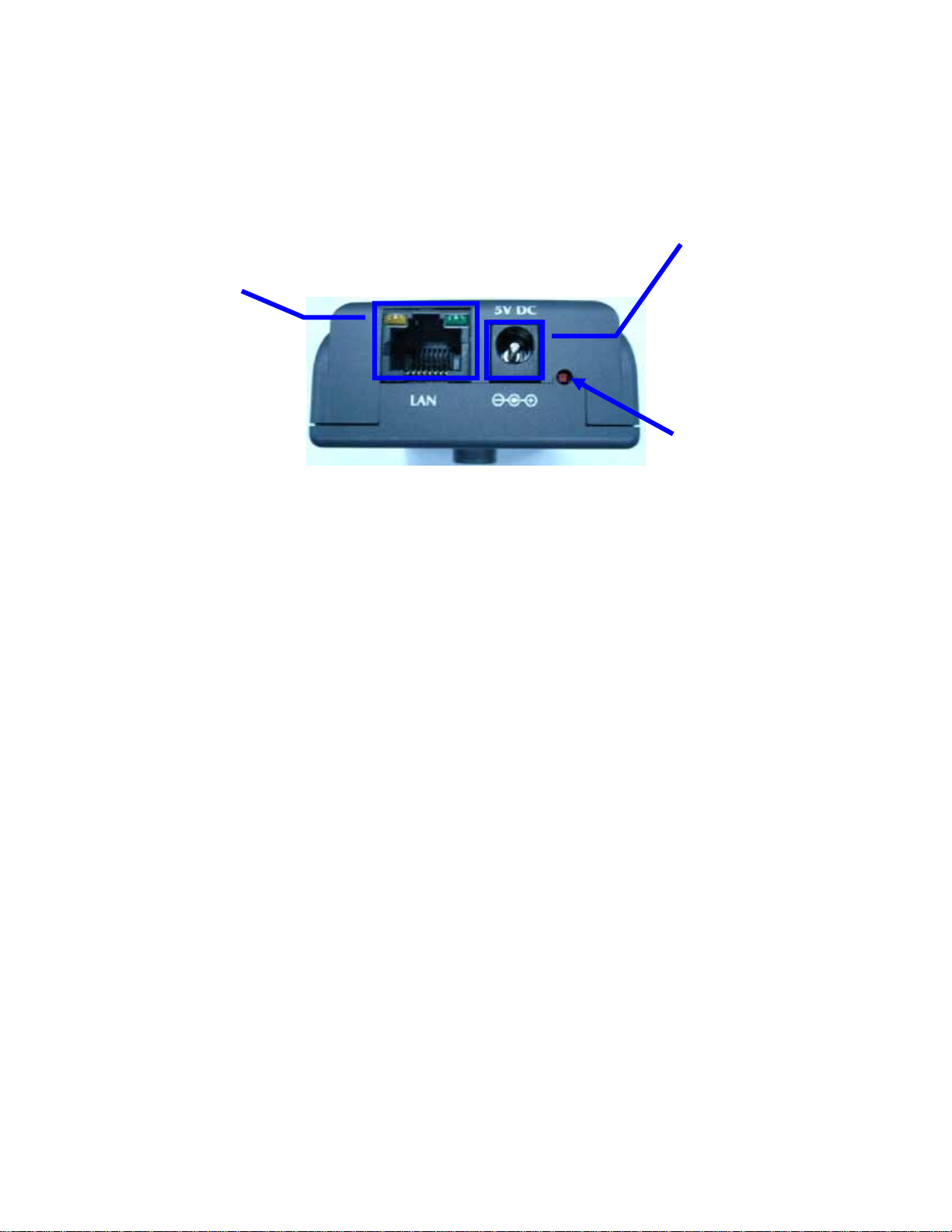
Chapter2 Hardware Connections
DC Power
Jack
LAN Socket
and LEDs
Factory
Default Reset
DC Power Jack
The DC power input jack is located on the Network Camera’s bottom. The input power is
5VDC. Note that supply the power to the Network Camera with standard power adapter
included in package. Otherwise, the improper power adapter may damage the unit and
result in danger.
LAN Socket
Beside the DC power Jack, the LAN socket is an RJ-45 connector for connections to
10Base-T or 100Base-TX Fast Ethernet cabling. Please use Category 5 “straight
through” cable to connect the Network Camera to an Ethernet network switch or hub.
10/100M Ethernet LEDs
LED stands for Light-Emitting Diode. The Ethernet LEDs are located on the RJ-45
connector. These LEDs are used to indicate the status of Network connection.
Factory Default Reset
This button is hidden in the pinhole under then Network Camera’s bottom. Please refer
to the Appendix A in this manual for more information.
7/60
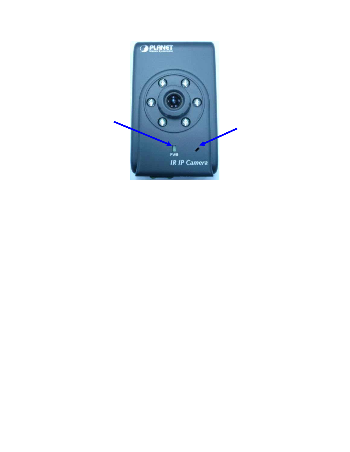
Status
LED
Microphone
Microphone
The Network Camera’s has built-in an internal microphone. This microphone is also
hidden in the pinhole located on the front panel.
Status LEDs
This LED is used to indicate the status of Network Camera.
8/60
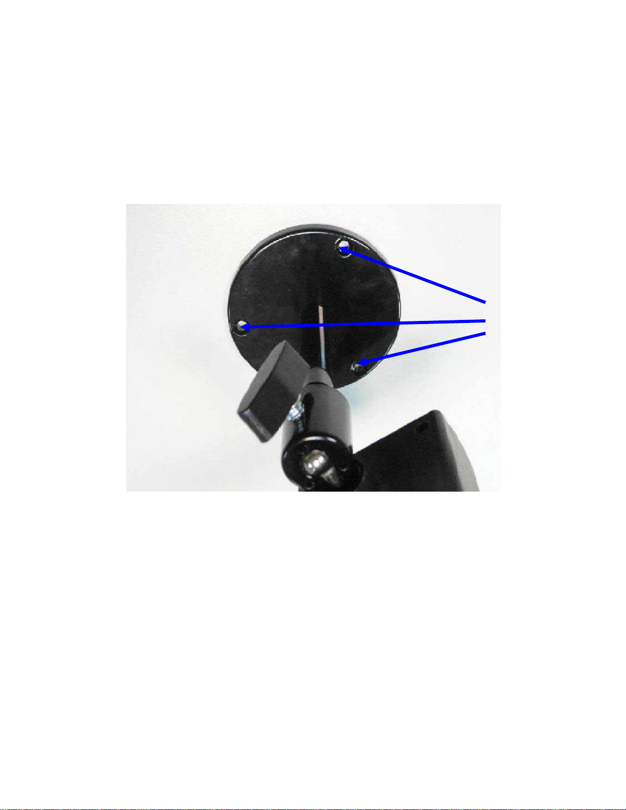
2.1Hardware Installation
1. Attach the Network Camera with the included stand
2. Place the Camera on the table or fix it onto ceiling or wall
Use screws to fix the Network Camera onto the ceiling or wall. You could also put
the Network Camera on the table directly.
Fixed it by
screws
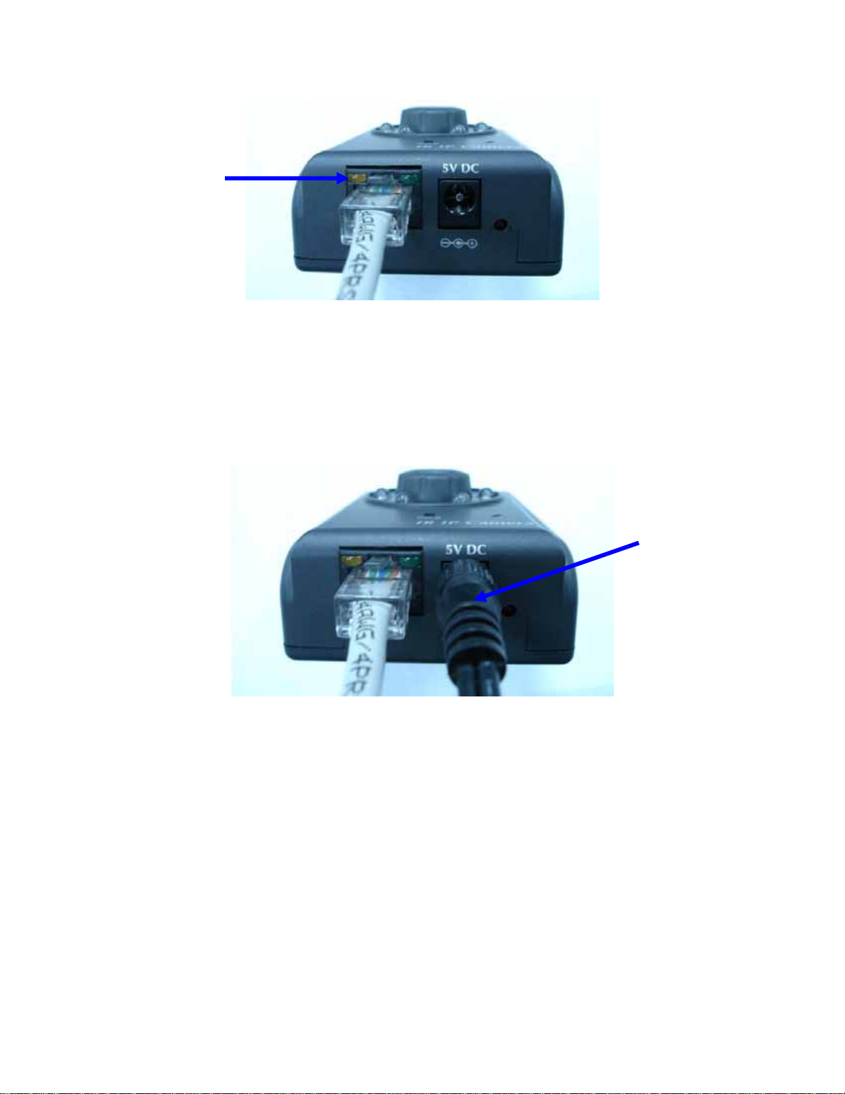
3. Plug an Ethernet cable into the Network Camera
Connect an Ethernet cable to the LAN socket located on the Network Camera’s bottom
and attach it to the network.
9/60
Ethernet
Cable
4. Connect the external power supply to Network Camera
Connect the external power supply to the DC power jack of the Network Camera. Note:
Use the power adapter, 5VDC, included in the package and connect it to wall outlet for
AC power.
Power
Cable
Once you have installed the Network Camera well and powered on, the status LED will
turn green first and then orange. It means the system is booting up successfully.
Furthermore, if you have a proper network connection, and access to the Network
Camera, the 10/100M LAN LED will flash green
10/60
Other manuals for ICA-106
1
Table of contents
Other Planet IP Camera manuals

Planet
Planet ICA-5250V User manual

Planet
Planet ICA-4200V User manual

Planet
Planet ICA-HM830W User manual

Planet
Planet ICA-108 User manual

Planet
Planet ICA-601 User manual

Planet
Planet ICA-230 User manual

Planet
Planet ICA-500 User manual

Planet
Planet ICA-500 User manual

Planet
Planet ICA-5250V User manual

Planet
Planet ICA-100 User manual

Planet
Planet ICA-500 User manual

Planet
Planet ICA-151 User manual

Planet
Planet ICA-310 User manual

Planet
Planet ICA-3110 User manual

Planet
Planet ICA-100C User manual

Planet
Planet ICA-2250VT User manual

Planet
Planet ICA-310 User manual

Planet
Planet ICA-3110 User manual

Planet
Planet ICA-501 User manual

Planet
Planet ICA-500C User manual


