
PCI MTSE Instruction manual

Multi-Trans
Smart Ecosystem
MTSE
Installation, Operation
& Maintenance Manual

DRAFT MTSE IO&M Manual
ii
Paragon Controls Inc,
Rev J 2/3/2021
TABLE OF CONTENTS
1.
INTRODUCTION .............................................................................................................................. 1
1.1.
Description ................................................................................................................................... 1
1.2.
Specifications ............................................................................................................................... 1
1.3.
Safety ............................................................................................................................................ 1
1.3.1.
Electrical Connections .......................................................................................................... 1
1.3.2.
Static Electricity ................................................................................................................... 1
2.
INSTALLATION ............................................................................................................................... 2
2.1.
Product Installation Dimensions .................................................................................................. 2
2.2.
Electrical Connections.................................................................................................................. 3
2.2.1.
Common Electrical Connections .......................................................................................... 4
2.3.
Pneumatic Connections ................................................................................................................ 7
3.
MTSE CONFIGURATIONS .............................................................................................................. 8
3.1.
Display Overview ......................................................................................................................... 8
3.2.
System Configurations ................................................................................................................. 9
3.2.1.
Display Types ..................................................................................................................... 10
3.3.
Display Features ......................................................................................................................... 11
3.3.1.
Sensor Data Page Shortcut ................................................................................................. 11
3.3.2.
Keypad ................................................................................................................................ 11
4.
MENU INFORMATION .................................................................................................................. 12
4.1.
Levels of Menus ......................................................................................................................... 12
4.2.
Setup Menus ............................................................................................................................... 13
4.2.1.
Operating Range Menu ...................................................................................................... 15
4.2.2.
K-Factor .............................................................................................................................. 16
4.2.3.
Analog I/O Configuration .................................................................................................. 17
4.2.4.
System Filters ..................................................................................................................... 17
4.2.5.
Network Communications .................................................................................................. 18
4.2.6.
Temperature Compensation & Altitude ............................................................................. 19
4.2.7.
Alarm Options .................................................................................................................... 20
4.2.8.
Units and Precision ............................................................................................................. 22
4.2.9.
ΔP Settings ......................................................................................................................... 23
4.3.
Diagnostics Menu ....................................................................................................................... 24
4.3.1.
Sensor Data Page ................................................................................................................ 24
4.3.2.
System Overview ............................................................................................................... 26
4.3.3.
Factory Defaults ................................................................................................................. 27
4.3.4.
Software Update ................................................................................................................. 27
4.3.5.
ScreenSaver ........................................................................................................................ 28
4.3.6.
AutoZero Settings ............................................................................................................... 28
4.4.
K-Factor Page Shortcut .............................................................................................................. 29
4.5.
Notification Page ........................................................................................................................ 29
4.6.
Troubleshooting and Help Pages................................................................................................ 31
ATTACHMENTS
A BACnet PROTOCOL IMPLEMENTATION CONFORMANCE STATEMENT
B MODBUS SOFTWARE CONFIGURATION PARAMETERS

DRAFT MTSE IO&M Manual
1
Paragon Controls Inc,
Rev J 2/3/2021
1. INTRODUCTION
1.1. Description
The Multi-Trans Smart Ecosystem (MTSE) is a flow and pressure transmitter which can simultaneously
provide airflow measurement of up to three flow systems (e.g., supply, return, and outside air) and four
differential pressure points (e.g., total fan static, duct static, pre and final filters) in any combination for
a total of 9 sensing points. The MTSE can connect to and receive a differential pressure signal from
each fan’s piezometer-ring airflow sensors or field installed airflow stations. This signal is scaled and
linearized before being displayed locally and transmitted out as a 4-20mA or 0-10VDC signal, as well as
on Modbus or BACnet network communication. A true AutoZero feature corrects potential zero offset
caused by large ambient temperature changes for outside air applications. A temperature compensation
feature compensates the flow signal for density changes caused by variations in the air temperature.
1.2. Specifications
Power Requirements 20 - 28VAC/VDC Supported Protocols BACnet MS/TP
Modbus RTU Slave
Protection Circuit Polarity Protected
Self-Resetting Fuse
Max communication length 4000 ft. (EIA-485)
Power Consumption 8.5W, 15.3VA Max
Operating Temperature -20°F to 158°F
(-29°C to 70°C)
Digital Outputs (2) Open Collector Digital
Outputs
Temperature Compensated Range -4°F to 158°F
(-20°C to70°C)
Digital Inputs (2) Dry Contact Digital Inputs Storage Temperature -40°F to 257°F
(-40°C to 125°C)
Analog Outputs (4) 16-bit Analog Outputs
Field Selectable 0-10V & 4-20mA
Overvoltage and Overcurrent Protected
Enclosure Impact Resistant Polycarbonate
IP-66, NEMA 4X Rated
Fire Retardant UL 94 V-0
Analog Inputs (4) 12-bit Analog Inputs
Field Selectable 0-5V, 0-10V & 4-20mA
Dimensions 9.50" L x 5.69" W x 3.56" H
Terminal Blocks Pluggable Screw Type
16 to 24 AWG
Pressure Connections 1/4" OD Barbed
Brass Fittings
Accuracy +/- 0.25% F.S.
1.3. Safety
1.3.1. Electrical Connections
Before any electrical connections are made, ensure the POWER SWITCH is in the OFF position.
1.3.2. Static Electricity
The circuit board contains components which are susceptible to damage caused by static electrical
discharge. Should it be necessary to remove the circuit board from the enclosure, appropriate
precautions must first be taken to ensure that the operator and the circuit board are at the same electrical
potential.

DRAFT MTSE IO&M Manual
2
Paragon Controls Inc,
Rev J 2/3/2021
2. INSTALLATION
The MTSE is rated for either indoor or outdoor installation. When installed outdoors, do not install the
MTSE where the display screen is in direct sunlight. Avoid locations that are subject to high
vibration.
2.1. Product Installation Dimensions
Figure 2.1 – MTSE Enclosure
DRAFT MTSE IO&M Manual
3
Paragon Controls Inc,
Rev J 2/3/2021
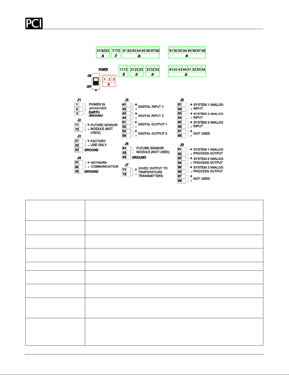
2.2. Electrical Connections
Figure 2.2 – Terminal Block Description
J1 – Power In The MTSE can be powered with 24VAC or 24VDC. Allowable range is
20-28V. Pin 1 on the power supply terminal is the positive leg, however the
device is reverse polarity protected.
J2 – Future Sensor
Module Expansion
Additional remote MTSE units will be daisy-chained together to expand the
sensing capability to 40 sensing points. Currently not available.
J3 - Service
Communication
Communication pins for Factory programming. DO NOT CONNECT TO
THESE PINS.
J4 - Network
Communication
BACnet/Modbus communication pins.
J5 - Digital Inputs
and Digital Outputs
Not Used
J6 - Future Sensor
Module Expansion
Will provide power for additional MTSE sensor module units. Currently
not available.
J7 - 24VDC Output to
Temp. Transmitters
Supplies power for external temperature transmitter(s).
J8 - Analog Inputs
Analog Inputs are tied to the temperature inputs and are scaled to the
minimum and maximum values set in Temperature Compensation &
Altitude Setup Menus.
J9 - Analog Outputs
System 1 Analog Process Output is System 1 Total Summed Flow (Process
Value) of the sensors in System 1. This is scaled to the Operating Range set
in the Setup Menus where 0V or 4 mA is 0 flow and 10V or 20 mA is the
operating range.

DRAFT MTSE IO&M Manual
4
Paragon Controls Inc,
Rev J 2/3/2021
2.2.1. Common Electrical Connections
PCI recommends cable should be low capacitance, shielded 22 or 24 AWG twisted wire for all electrical
connections. When connecting multiple MTSE units on a common communication network, connect
shielding wires together and connect only one side of the shielding wire to earth ground at the building
automation system; do not connect both ends of the shield wire to earth ground.
Figure 2.3 – Typical 1 System connection to 24VAC/DC power, 4-20mA loop-powered
temperature transmitter, analog receiving device, or network communication.

DRAFT MTSE IO&M Manual
5
Paragon Controls Inc,
Rev J 2/3/2021
Figure 2.4 – Typical 3 System connection to 24VAC/DC power, 4-20mA loop-powered
temperature transmitters, analog receiving devices, or network communication.

DRAFT MTSE IO&M Manual
6
Paragon Controls Inc,
Rev J 2/3/2021
Figure 2.5 – Typical 3 System connection to 24VAC/DC power, 0-10V three-wire temperature
transmitters, analog receiving devices, or network communication.

DRAFT MTSE IO&M Manual
7
Paragon Controls Inc,
Rev J 2/3/2021
SENSOR 5
SENSOR 2
SENSOR 3
SENSOR 1
SF-1
SF-2
RF-1
RF-2
OA-1
2.3. Pneumatic Connections
The MTSE can measure a maximum of five airflow points in up to three systems and monitor up to four
ΔP points for a total of 9 sensing points. Two pneumatic plenum-rated signal tubing lines are required
to be connected to the MTSE for each sensing point, a high (or Total) and a low (or Static) connection.
Transducers in the MTSE are numbered sequentially; therefore, all connections for System 1 must be
made in order starting at Sensor 1, and then System 2 will start immediately after the last sensor in
System 1, and so on. See label inside cover of MTSE for sensor numbering. Shown below is an
example of an MTSE configured to measure two Supply Fans, two Return Fans, and a single Outside
Air opening.
Figure 2.6 – Typical pneumatic connections to piezometer rings
on fans and flow measurement station
SENSOR 4

DRAFT MTSE IO&M Manual
8
Paragon Controls Inc,
Rev J 2/3/2021
3. MTSE CONFIGURATIONS
The MTSE can be configured to measure airflow in up to 3 unique Systems and monitor up to 4
additional differential pressure (ΔP) points up to a total of 9 sensing points.
3.1. Display Overview
Shown below is a fully loaded MTSE monitoring (3) independent systems and (4) ΔPs.
Figure 3.1 – Normal Active Display showing 3 Systems and 4 ΔP measurement points.
1) System Number: Static text indicating the specific system number.
2) System Tagging: Custom entered tagging information for a more meaningful representation of
where measurement is taking place.
3) System Measurement: Live measurement of flow, velocity, or pressure for the System.
4) System Bar Graph: 0 to 100% graphical representation of System Measurement. 100% represents
Operating Range (Max).
5) Units: Field selectable units for the System Measurement.
6) Max Operating Range: Upper limit of allowed flow measurement value. System Bar graph and
System Analog Output are scaled to this value (Max = 10V or 20mA).
7) Temperature: System Temperature reading from Input source.
8) ΔP1 Tag: Customer field entered tagging information for individual, non-System measured
differential pressures.
9) ΔP Pressure Measurement: Live measurement of individual, non-System measured pressures.
10) ΔP Alarm Value: Field adjustable alarm setpoint value for ΔP Pressure Measurement. Can be high
or low triggered setpoint.
11) Setup Menus
12) Diagnostics Menus
13) K-Factor Menu Shortcut
14) Notification: Alarms and Warning Notifications
15) (?) Troubleshooting and Support Pages
Other manuals for MTSE
1
Table of contents
Other PCI Measuring Instrument manuals


