
Nic WA-5F User manual

WA-5F Service Manual
Document
Number NIC-704-2015-01 Date of
Issue Apr. 14, 2017
Control
Department Technical Center Page 1/36
1
WA-5F
Service Manual
Nippon Instruments Corporation
Technical Center
Date Prepared
Checked Approved
First Edition
Apr. 14, 2017
Kinoshita
Yamada Kato

WA-5F Service Manual
Document
Number NIC-704-2015-01 Date of
Issue Apr. 14, 2017
Control
Department Technical Center Page 2/36
2
Revision History
Revision No.
Revision Date
Reason for Changes
Prepared
Approved
01 Apr. 14, 2017 First Edition issued Kinoshita Kato
Distribution List
Destination Date Destination
Date Destination
Date
President -
Executive Director -
Application Technology Dept.
-
Sales Dept. -
R&D Dept. -

3
Atmospheric Mercury Analyzer
Mercury/WA-5F Service Manual
Contents
1. Introduction....................................................................................................................5
Overview ................................................................................................................5
Basic configuration of this system ..........................................................................5
Part names and functions of the Mercury Analyzer ................................................6
Front (inside front cover) .................................................................................6
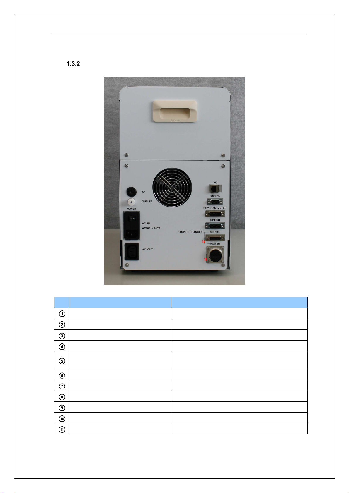
Back................................................................................................................7
Internal components viewed from the right......................................................8
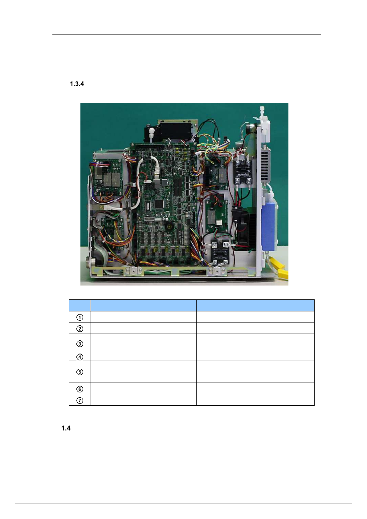
Internal components viewed from the left........................................................9
Intended readers of this Service Manual................................................................9
2. Safety instructions.......................................................................................................10
Meaning of safety alert symbols...........................................................................10
Cautions on installation ........................................................................................10
Cautions on maintenance.....................................................................................10
3. Maintenance................................................................................................................11
Inspection items ...................................................................................................11
Daily inspection.............................................................................................11
Annual inspection..........................................................................................12
Errors and warnings .............................................................................................13
Troubleshooting....................................................................................................16
Decrease in sensitivity...................................................................................16
Abnormal blank value....................................................................................17
Abnormal increase in sensitivity....................................................................17
Maintenance.........................................................................................................18
Leak check....................................................................................................18
Replacing the septum....................................................................................19
Cleaning the gas scrubbing bottle and dehumidifying bottle .........................19
Detaching and attaching the cover................................................................20
Detaching and attaching the collector tube (H2)............................................20
Cleaning the absorption cell..........................................................................21
Cleaning the joints.........................................................................................22

4
How to reduce the blank value of collector tubes..........................................23
4. How to remove and install the components.................................................................24
Collector tube adaptor..........................................................................................24
Heater H1.............................................................................................................24
Heater H2.............................................................................................................26
Gas scrubbing bottle and dehumidifying bottle.....................................................26
Cell.......................................................................................................................26
Adjusting the sensitivity of the optical system.......................................................27
Mercury lamp........................................................................................................29
Photoelectric tube preamplifier.............................................................................31
Second collector tube...........................................................................................31
Solenoid valve and active carbon filter.................................................................32
Flow sensor..........................................................................................................33
Air pump...............................................................................................................33
Control boards......................................................................................................34
Switching power supply........................................................................................35

5
1. Introduction
Ensure to refer to this Service Manual before conducting the inspection, repairs, or
maintenance of the Mercury Analyzer WA-5F.
Overview
The Mercury/WA-5F is a mercury measuring system which allows the amount of
mercury collected in a dedicated mercury collector tube to be quickly measured with
high sensitivity and in a wide range through simple operations.
The operations are carried out on a PC where the measurement results can be
analyzed through various methods such as statistical calculations.
Basic configuration of this system
This system consists of the following:
(1) Mercury Analyzer: WA-5F
(2) Data analysis / System control software: WA5Win
(3) Standard accessories
(4) Personal computer

6
Part names and functions of the Mercury Analyzer
* This section is identical to the content in the Instruction Manual.
Front (inside front cover)
No.
Item Remarks
Standard gas inlet Comes with a built-in septum.
Heating furnace (H1) for collector tube Comes with a built-in cooling fan.
Mounting port for collector tube Made of fluoride resin.
Electronic cooling unit
Gas scrubbing bottle
Removes any acidic gas.
- For measuring the mercury in the
ambient air:
the standard buffer solution (1+1), pH
6.86
- For measuring the mercury in the
samples of reducing vaporization:
NaOH, 0.1M
Dehumidifying bottle Removes moisture.
Opening for connecting to the detector
Valve for connecting optional units (EV)
Flow control needle valve Adjusted to 0.5 L/min.
1
2
3
4
5
6
7
9
8
7
Back
No.
Item Remarks
OUTLET Connection port for outlet gas tube (O.D.: 6 mm)
Main power switch
Connection port for power cable 100-240 VAC
Fuse 100V 10A or 250V 5A
AC OUT Power outlet for Auto Tube Changer
* Linked with the main switch.
LAN port for PC connection Port for a LAN cable.
Serial port (Not used)
Connection port for dry gas meter
Option (Not used)
Auto Tube Changer (Signal) Port for control signal cable
Auto Tube Changer (Power) Port for power cable
1
2
3
4
5
6
7
8
9

8
Internal components viewed from the right
No.
Item Remarks
Valve V1 Switches between the sampling/detection
lines.
Re-collecting furnace (H2) Comes with a built-in cooling fan.
Valve V2 Switches between the detection/bypass
lines.
Valve VF Prevents backflow.
Air pump
Flow control needle valve Adjusted to 0.5 L/min.
Flow sensor For measuring the flow rate
Active carbon for carrier gas For purging carrier gas during
transfer/sampling
Active carbon for carrier gas For purging carrier gas during measurement
Active carbon for outlet gas For removing mercury from the outlet gas
after measurement
9
Internal components viewed from the left
No. Item Remarks
Main circuit board
SSR1 For controlling the H1
SSR2 For controlling the H2
Power board for optical system
Power board for electronic cooling
unit
Power board for main circuit board
MFC control board
Intended readers of this Service Manual
The intended readers of this manual are engineers who have received proper training
and will be dispatched to a site or work at a factory to conduct the inspection, repairs,
or maintenance of the system.
6
1
2
3
4
5
7

10
2. Safety instructions
Observe the following instructions to ensure safety.
Meaning of safety alert symbols
Warning
indicates safety instructions required to prevent severe injury
or death.
Caution indicates safety instructions required to prevent moderate or
minor injury or property damage.
Cautions on installation
Warning
• To prevent an electric shock, be sure to connect the grounding wire.
• To prevent an electric shock and fire, be sure to check the power cables
and plugs for any damage.
Cautions on maintenance
Warning
• Shut off the power supply before starting the maintenance work.
Otherwise, you may suffer an electric shock.
Caution
• Conduct the maintenance of the heater section only after the power has
been turned off and the heater has cooled down. Otherwise, you may burn
yourself.
• Be careful when touching any glass parts. Otherwise, you may get injured
if they are broken.
• Be sure to discharge any liquids accumulated in the drain tank once the
work is complete. In addition, before starting the discharge, be sure to turn
off the power.
Other manuals for WA-5F
1
Table of contents
Other Nic Measuring Instrument manuals


