montwill M2-14 User manual

User manual M2
Alternating voltage / Alternating current signal rms-value (TRMS)
0-50 VAC, 0-10 VAC, 0-1 AAC, 0-5 AAC
96x48M2_14GB.pdf update: 28.05.2020
Technical features:
• red display of -19999…99999 Digits (optional: green, orange, blue)
• installation depth: 70 mm without plug-in terminal
• min/max-memory
• 30 adjustable supporting points
• display flashing at threshold value exceedance / undercut
• digital input for triggering of Hold, Tara
• permanent min/max value recording
• volume metering (totaliser)
• mathematical functions like reciprocal value, square roots, squaring or rounding
• setpoint generator
• sliding averaging
• brightness control
• programming interlock via access code
• protection class IP65 at the front
• pluggable screw terminal
• optional galvanic insulated digital input or analog output
• optional 2 relay outputs
• accessories: PC-based configuration kit PM-TOOL incl. CD and USB-adapter for devices
without keypad and for a simple adjustment of standard devices

Identification
STANDARD-TYPES ORDER NUMBER
AC current, AC voltage
Housing size: 96x48 mm
M2-1VR5B.0004.570xD
M2-1VR5B.0004.670xD
Please state physical unit by order, e.g. A.
Options – breakdown of order code:
M 2- 1 V R 5 B. 0 0 0 4. 6 7 2 x D
Basic type M2 Dimension
D physical unit
Installation depth
89 mm 2 Version
incl. plug-in terminal x internal version
Housing size Switching points
B96xH48xT70 mm 1 0 no switching point
2 2 relay outputs
Type of display
V, A V Protection class
1 without keypad,
Display colour operation via PM-TOOL
Blue B 7 IP65 / plug-in terminal
Green G
Red R Voltage supply
Yellow Y 4 115 VAC
5 230 VAC
Number of digits 6 10-30 VDC
5-digit 5
Measuring input
Digit height 4 AC current /
14 mm BAC voltage TRMS
Digital input Analog output
without 0 0 without
one I X 0-10 VDC, 0/4-20 mA
Sensor supply
0 without

Contents
1. Brief description 1
2. Assembly 2
3. Electrical connection 3
4. Description of function and operation 4
4.1. Programming software PM-TOOL 5
5. Setting up the device 6
5.1. Switching on 6
5.2. Standard parameterisation (flat operation level) 6
Value assignment for the triggering of the signal input
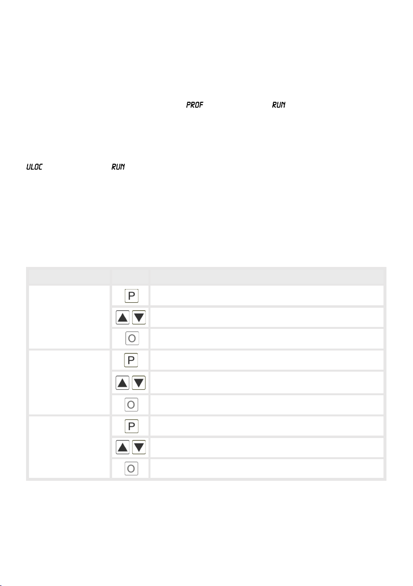
5.3. Programming interlock 9
Activation/Deactivation of the programming interlock or change into
professional or flat operation level
5.4. Extended parametersation (professional operation level) 10
5.4.1. Signal input parameters 10
Value assignment for the triggering of the signal input incl. linearisation
5.4.2. General device parameters 13
Superior device functions like Hold, Tara, min/max permanent, setpoint value function /
nominal value function, averaging, brightness control, suppression of negative offsets,
as well as the control of the digital input and keyboard layout
5.4.3. Safety parameters 19
Assignment of user and master code to lock or to receive access to defined parameter
such as analog output and alarms, etc.
5.4.4. Analog parameters 20
Analog output functions
5.4.5. Relay functions 22
Parameter for setpoint definition
5.4.6. Alarm parameters 25
Actuator and dependencies of the alarms
5.4.7. Totaliser (Volume metering) 27
Parameter for calculation of the sum function
6. Reset to factory settings 28
Reset parameters onto the delivery state
7. Alarms / Relays 29
Functional principle of the switching outputs
8. Sensor aligment 31
Diagram of functional sequences for sensors with existing adjustable resistor
9. Technical data 32
10. Safety advices 34
11. Error elimination 35

1. Brief description
1
1. Brief description
The panel meter instrument M2-14 is a 5-digit device for AC current / AC voltage signals
(TRMS) and a visual threshold value monitoring via the display. The configuration happens
via four keys at the front or by the optional PC software PM-TOOL. The integrated
programming interlock prevents unrequested changes of parameters and can be unlocked
again with an individual code. Optional the following functions are available: a digital input for
triggering of Hold (Tara), aswell as one analog output for further evaluating in the unit.
With help of the galvanic isolated setpoints (optional), free adjustable limit values can be
controlled and reported to a superior master display.
The electrical connection is done via plug-in terminals on the back side.
Selectable functions like e.g. the recall of the min/max-value, an averaging of the measuring
signals, a nominal presetting or setpoint presetting, a direct threshold value regulation during
operation mode and further measuring setpoints for linearisation, complete the modern
device concept.

2. Assembly
2
2. Assembly
Please read the Safety advices on page 34 before installation and keep this user manual for
future reference.
1. After removing the fixing elements, insert the device.
2. Check the seal to make sure it fits securely.
3. Click the fixing elements back into place and tighten the clamping screws by hand. Then use
a screwdriver to tighten them another half a turn.
CAUTION! The torque should not exceed 0.1 Nm!
The dimension symbols can be exchanged before installation via a channel on the side!
Sealing
48,0
3,0
M2
Gap for physical unit
89,0

3. Electrical connection
3
3. Electrical connection
Type M2-1VR5B.0004.470xD supply of 115 VAC
Type M2-1VR5B.0004.570xD supply of 230 VAC
Type M2-1VR5B.0004.670xD supply of 10-30 VDC
0-5 AAC
+
0...1 AAC
_
+
1 2 3 10 1194 5 6 7 8
0-10 VDC
Digital
input
(Option)
NL
7 8 9
_+
0/4-20 mA
Analog output
(Option)
21 22 23 24 25 26
S1 S2
Relay option
0...10 VAC
_
+
0...50 VAC
_
+
_+
10-30 VDC
or
115 VAC
or
230 VAC
7 8 9
Digital input
10-30 VDC
_+
M2 with digital input and external
voltage supply source

4. Description of function and operation
4
4. Description of function and operation
Operation
The operation is divided into three different levels.
Menu level (delivery status)
This level is designed for the standard settings of the device. Only menu items which are
sufficent to set the device into operation are displayed. To get into the professional level, run
through the menu level and parameterise under menu item .
Menu group level (complete function volume)
Suited for complex applications as e.g. linkage of alarms, setpoint treatment, totaliser function
etc.. In this level function groups which allow an extended parameterisation of the standard
settings are availabe. To leave the menu group level, run through this level and parameterise
under menu item .
Parameterisation level:
Parameters deposited in the menu item can here be parameterised. Functions that can be
changed or adjusted, are always signalised by a flashing of the display. Settings that are
made in the parameterisation level are confirmed with [P] and thus saved. By pressing the
[O]-key („zero-key“) it leads to a break-off of the value input and to a change into the menu
level. All adjustments are saved automatically by the device and changes into operating
mode, if no further key operation is done within the next 10 seconds.
Level Key Description
Menu level
Change to parameterisation level and deposited values.
Keys for up and down navigation in the menu level.
Change into operation mode.
Parameterisation
level
Confirms the changes made at the parameterisation level.
Adjustment of the value / the setting.
Change into menu level or break-off in value input.
Menu group level
Change to menu level.
Keys for up and down navigation in the menu group level.
Change into operation mode or back into menu level.

5
4. Description of function and operation
Function chart:
4.1 Parameterisation software PM-TOOL:
Part of the PM-TOOL are the software on CD and an USB-cable with device adapter. The
connection happens via a 4-pole micromatch-plug on the back side of the device, to the
PC-side the connection happens via an USB plug.
System requirements: PC incl. USB interface
Software: Windows XP, Windows VISTA
With this tool the device configuration can be generated, omitted and saved on the PC. The
parameters can be changed via the easy to handle program surface, whereat the operating
mode and the possible selection options can be preset by the program.

6
5.1. Switching on
Once the installation is complete, start the device by applying the voltage supply. Before,
check once again that all electrical connections are correct.
Starting sequence
For 1 second during the switching-on process, the segment test ( ) is displayed
followed by an indication of the software type and, after that, also for 1 second the software
version. After the starting sequence, the device switches to operation/display mode.
5.2. Standard parameterisation: (Flat operation level)
To parameterise the display, press the [P]-key in operating mode for 1 second. The display
then changes to the menu level with the first menu item .
5. Setting up the device
Menu level Parameterisation level
Selection of the input signal,
Default:
Available as measuring input options are 0-50 VAC/0-10 VAC or 0-5 AAC/0-1 AAC
signals as works calibration (without application of the sensor signal) and
and as sensor calibration (with the sensor applied). Select with
[▲] [▼] and confirm the selection with [P].
Setting the end value of the measuring range, :
Default:
Set the end value from the smallest to the highest digit with [▲] [▼] and confirm
each digit with [P]. A minus sign can only be parameterized on the highest value
digit. After the last digit, the display switches back to the menu level. If was
selected as input option, one can only select between and With , only
the previously set display value is taken over, and with , the device takes over
both the display value and the analogue input value.

7
5. Setting up the device
Menu level Parameterisation level
Setting the start/offset value of the measuring range, :
Default:
Enter the start/offset value from the smallest to the highest digit with [▲] [▼] and
confirm each digit with [P]. After the last digit the display switches back to the
menu level. If was selected as input option, one can only select between
and With , only the previously set display value is taken over, and with ,
the device takes over both the display value and the analogue input value.
Setting the decimal point, :
Default:
The decimal point on the display can be moved with [▲] [▼] and confirmed with
[P]. The display then switches back to the menu level again.
Setting up the display time, :
Default:
The display time is set with [▲] [▼]. The display moves up in increments of 0.1 up
to 1 second and in increments of 1.0 up to 10.0 seconds. Confirm the selection by
pressing the [P] button. The display then switches back to the menu level again.
Selection of analog output,
Default:
Three output signals are available: 0-10 VDC, 0-20 mA and 4-20 mA, with this
function, the demanded signal is selected.
Setting up the final value of the analog output,
Default:
The final value is adjusted from the smallest digit to the highest digit with [▲] [▼]
and digit by digit confirmed with [P]. A minus sign can only be parameterised on
the highest digit. After the last digit, the device changes back into menu level.
then
Table of contents
Other montwill Measuring Instrument manuals

montwill
montwill M3-F User manual

montwill
montwill M1 User manual

montwill
montwill M3-34H User manual

montwill
montwill M2-1F Series User manual

montwill
montwill M2 Series User manual

montwill
montwill M1 User manual

montwill
montwill MB2-2V User manual

montwill
montwill M1 User manual

montwill
montwill M3 Series User manual

montwill
montwill M3 Series User manual


