
METER TEROS 54 User manual

i
TABLE OF CONTENTS
1. Introduction.............................................................................................. 1
2. Operation ...................................................................................................2
2.1 Installation ................................................................................................2
2.1.1 Overview ..........................................................................................2
2.1.2 Installation Methods........................................................................6
2.2 Connecting............................................................................................... 11
2.2.1 Connect to METER Data Logger...................................................... 12
2.2.2 Connect to Non-METER Data Logger.............................................. 12
2.3 Communication ....................................................................................... 14
2.4 Removal................................................................................................... 15
3. System....................................................................................................... 20
3.1 Specifications.......................................................................................... 20
3.2 Components ............................................................................................ 24
3.3 Theory...................................................................................................... 27
3.3.1 Volumetric Water Content.............................................................. 27
3.3.2 Temperature .................................................................................. 27
4. Service....................................................................................................... 28
4.1 Calibration ............................................................................................... 28
4.1.1 Mineral Soils.................................................................................. 28
4.1.2 Apparent Dielectric Permittivity .................................................... 29
4.2 Maintenance............................................................................................ 29
4.3 Troubleshooting....................................................................................... 29
4.4 Customer Support.................................................................................... 31
4.5 Terms and Conditions .............................................................................. 31
18511-00
3.2023



1
TEROS 54
1. INTRODUCTION
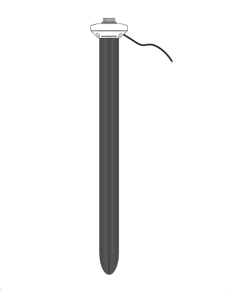
Thank you for choosing the TEROS 54 Soil Water Content Profile probe from METER Group.
The TEROS 54 probe is designed to be installed in mineral soils, a variety of growing media,
and other porous materials. This manual describes how to use the probe and guides the
customer through the probe features.
The TEROS 54 probe is an accurate tool for monitoring volumetric water content (VWC)
using capacitance and frequency-domain technology. The sensors use a 70 MHz frequency
to minimizes textural and salinity effects that makes the TEROS 54 accurate in most
mineral soils.
The TEROS 54 uses four precision-integrated temperature sensors to measure temperature
in soil and soilless substrates.
Verify all TEROS 54 components are included and appear in good condition:
1. TEROS 54 probe
2. Protective cap
METER recommends testing sensors with the data aquisition device and software before
going to the field.

2
OPERATION
2. OPERATION
Please read all instructions before operating the TEROS 54 to ensure it performs to its full
potential.
PRECAUTION
METER sensors are built to the highest standards, but misuse, improper protection, or improper installation may
damage the sensor and possibly void the manufacturer’s warranty. Before integrating TEROS 54 into a system, make
sure to follow the recommended installation instructions and have the proper protections in place to safeguard
sensors from damage. If installing sensors in a lightning-prone area with a grounded data logger, see the application
note Lightning surge and grounding practices.
2.1 INSTALLATION
This sections contains an overview of the TEROS 54 installation procedure (Section2.1.1)
and detailed information about the pile (slide) hammer (Section2.1.2)
2.1.1 OVERVIEW
Table1 contains information needed to install the TEROS54 and start collecting data.
Table1 Installation
Tools Needed
TEROS 54 auger
Dead blow hammer
Pile hammer (slide hammer)
PVC casing or flexible conduit (to protect cables)
Level (to check that the auger is level while digging the hole for the probe)
Preparation
Consider the Surroundings
When selecting a suitable location for the TEROS 54, make sure that it is a
representative location in the measurement area.
Avoid installation in very rocky soils, if possible, to prevent damage to the
TEROS 54.
Conduct System Check
Plug the probe into the logger (Section2.2) to make sure the probe is functional.
Check Sensor Functionality
Verify all sensors read within expected ranges. To validate both probe
and logger functionality, take probe measurements in air and water.
The value of permittivity in air should be 1.
NOTE: The sensors will not read 100% water content in water.

3
TEROS 54
Table 1 Installation (continued)
Installation
Create Hole
To install the TEROS 54 into the soil, use the TEROS 54 auger available from
METER (Section2.1.2) to drill a vertical hole in the soil. Use a level on the auger
to make sure the hole is drilled vertically to prevent damage to the probe.
NOTE: METER recommends using the TEROS 54 auger and slide hammer that are designed
specifically for installing the TEROS 54 in compact, firm soil.This method will result in good
soil contact. The TEROS 54 can only be installed in very loose, sandy, and soft soils without
using the TEROS54 auger.
• Avoid interfering with large objects like roots or rocks that could potentially
damage the probe housing.
• Installations near large metal objects can affect the sensor's function and
distort readings.
NOTE: Never drill to the final depth in one step. Remove the soil from the auger
approximately every 30 cm.
Mark the required drilling depth on the TEROS 54 auger extension rod.
Themaximum depth the auger can go is 70 cm.
Auger
maximum digging
depth = 70 cm

4
OPERATION
Table 1 Installation (continued)
Installation
(continued)
Installation Tool
CAUTION
When using the slide hammer to install the TEROS 54 probe, please wear proper ear
protection to prevent hearing damagße because the hammer is quite loud. Please wear
gloves to protect hands from being pinched.
When the hole has been drilled to its final depth, position the TEROS 54
centered over the hole, tip-first, and press it down vertically.
NOTE: Do not try to insert the TEROS 54 to the desired depth by pushing down by hand.
For installation, METER highly recommends the slide hammer, available
from METER.
Place the slide hammer with the attachment on the TEROS 54 probe head and
drop the weight several times to install the TEROS 54 gradually into the soil.
Raise up
Drop down
slide hammer
drop weight
(slideable)
probe head
NOTE: During installation, make sure that no air gaps occur between soil and the probe
housing. Gaps, such as air pockets near the probe housing, can have a negative effect on
the measurement and falsify the measured values.
5
TEROS 54
Table 1 Installation (continued)
Installation
(continued)
Finally, screw the protective cap into the thread to protect it from
environmental influences.
NOTE: Do not hit the probe head directly with a hammer.This can damage the probe head.
Installation
(continued)
Secure and Protect Cables
NOTE: Improperly protected cables can lead to severed cables or disconnected probes.
Cabling issues can be caused by many factors such as rodent damage, driving over probe
cables, tripping over cables, not leaving enough cable slack during installation, or poor
probe wiring connections (Section2.1.2).
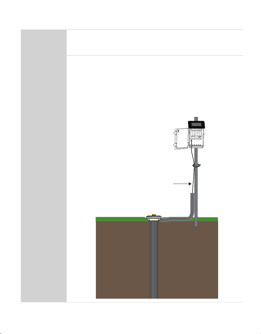
Install cables in conduit or plastic tubing when near the ground to avoid
rodent damage.
Gather and secure cables between the TEROS 54 and the data logger to the
mounting mast in one or more places.
Port1Port2Port3Port4 Port 5Port6
TEST
OK
ERROR
(-)
(-)(-) (-)
(-)(+)(-)(+)(+)
(+)(+)(+)
Cable

6
OPERATION
Table 1 Installation (continued)
Installation
(continued)
Connect to Logger
Plug the probe into a data logger.
Use the data logger to make sure the sensors are reading properly.
Verify that these readings are within expected ranges.
For more instructions on connecting to data loggers, refer to Section2.2.
2.1.2 INSTALLATION METHODS
This section explains installation methods METER recommends for different soil
conditions (Figure1).
The TEROS 54 probe can only be installed in very loose, sandy, and soft soils without the
TEROS54 auger.
METER recommends using the TEROS 54 auger and slide hammer that are designed
specifically for installing the TEROS 54 in compact, firm soil. This method will result in good
soil contact.
• The TEROS 54 auger is shaped to prevent soil compaction near the probe elements
(Figure2).
• The slide hammer (Figure3) consists of four parts: handle, rod, weight (approx. 4 kg
[8.82 lbs]) and connector (put on the TEROS 54 head). Because there is a predetermined
distance that the slide hammer weight travels when dropped, there is an even distribution
of force delivered.
Other manuals for TEROS 54
1
Table of contents
Other METER Measuring Instrument manuals

METER
METER SC-1 User manual

METER
METER G3 User manual

METER
METER SI-400 Series User manual

METER
METER APOGEE SU-221 User manual

METER
METER VARIOS User manual

METER
METER AQUALAB TDL User manual

METER
METER MW04 User manual

METER
METER AQUALAB 3 User manual

METER
METER AQUALAB User manual

METER
METER ROS 1 User manual

METER
METER ATMOS 22 User manual

METER
METER ATMOS 22 User manual

METER
METER TEROS 06 User manual

METER
METER AQUALAB PAWKIT User manual

METER
METER THERMOLINK User manual

METER
METER APOGEE SQ-521 User manual

METER
METER WP4C User manual

METER
METER AQUALAB VSA User manual

METER
METER SATURO User manual

METER
METER AQUALAB PAWKIT User manual


