Lakeside ALTO Mini Tower User manual

ALTO MEDIUM DUTY
MINI TOWER
Mobile Aluminium Access Tower
ISSUE 1
Instruction Manual EN 1298-IM-EN
The ALTO Mini Tower is compliant with BS EN 1004:2004
3T - Through The Trapdoor Method
Lakeside Industries Ltd
www.altoaccess.com

Page 2ALTO Mini Tower |Assembly Guide
Introduction
Please read these instructions carefully and ensure that you fully understand all of the information
contained herein. All of the information in this document is vital for the safe utilisation of your Alto Mini
Tower.
All Alto Access products are professional quality engineered equipment designed primarily with safety
in mind and meet or exceed all standards, recommendations and guidelines. Used properly, Alto access
equipment will keep you safe when working at height.
This manual contains all of the information necessary to correctly assemble your Alto Mini Tower and
incorporates all of the requirements of the PASMA 3T method of assembly as endorsed by the HSE.
This manual should be used in conjunction with your Risk Assessment and Method Statement and in
line with the Work at Height Regulations 2005 which place an obligation on employers to eliminate or
minimise risks. This manual must be made available to the user/assembler at all pertinent times.
Only competent and qualified personnel should undertake erection, dismantling or alteration, organisation,
planning or supervision of mobile access towers. In the case of any doubt, sufficient relevant additional
training must be given beforehand to ensure safe use. For further information on the use of mobile
access towers consult PASMA (www.pasma.co.uk; Tel +44 (0) 845 230 4041). For any additional technical
information or specific advice please contact the manufacturer Lakeside Industries Limited Tel: +44
only. User guides are also available to download from our website www.altoaccess.com.
Certifications
The Alto Mini Tower is a mobile access tower compliant with EN 1004 Class 3. This tower is not suitable for
applications outside of EN1004 or other than as described in these instructions. This tower is manufactured
in our ISO 9001 accredited facility. This manual complies with EN 1298-IM-EN.
Maximum Safe Working Loads
The safe working load of the tower is 350 kg including its own weight. The maximum safe working load
of any individual platform is 200 kg evenly distributed. If the tower is to be used in an application outside
the scope of EN1004, contact your supplier or the manufacturer, Lakeside Industries Limited, for advice

Page 3ALTO Access Products |Lakeside Industries Ltd
Inspection Care & Maintenance
Alto Access equipment is designed and manufactured to the highest standards in the industry and is
stronger, more robust and safer than any comparable competitor product. Properly cared for, it will give
a long and productive service life.
· The equipment should be inspected and maintained as outlined in the “ALTO MD Tower Inspection
Procedures”. A free downloadable copy is available at www.altoaccess.com/downloads.
· Equipment should always be inspected before and after each use.
· Whilst Alto Access equipment is extremely robust, care should be exercised in loading, transporting
and handling components to avoid damage or injury to either the equipment or persons.
· Repairs should only be carried out by Lakeside Industries Limited or their authorised repairers.
· In case of any doubt as to the integrity of any items of Alto Access equipment, the part should be
withdrawn from use, quarantined and subject to detailed examination to determine whether repair
or replacement is required. If returned to the factory, Lakeside Industries Limited will provide a free
of charge evaluation of any damaged components.
Safety
Check that all of the necessary components and equipment for the particular tower configuration to be
built are on site, undamaged and functioning correctly. Damaged or incorrect components must not be
used.
· Check that the surface on which the tower is to be located is capable of supporting the tower and its
payload.
· The safe working load of the tower is 350 kg including its own weight. The maximum safe working
load of any individual platform is 200 kg evenly distributed.
· Towers must always be climbed from the inside using the built in ladders only. If the work carried
out from the tower requires frequent carrying of equipment and materials up or down the tower, an
Alto stair tower should be used in preference to a ladderspan tower.
· The tower must be levelled when erected using the adjustable jack or castor legs.
· It is recommended that the tower be tied in when left unattended.
· Never use other makes or types of tower component when assembling an Alto Mini Tower.
· The Alto Mini Tower has been designed for single person use. If the tower is to be used with two
operatives, larger stabilisers or suitable alternative stabilisation methods must be used.

Page 4ALTO Mini Tower |Assembly Guide
· Always comply with the Work at Height Regulations 2005 when erecting, dismantling & using the
tower.
· See “Moving the Tower” below for safety guidelines affecting the relocation of the tower.
· Beware live electrical installations, cables, moving machinery or other obstructions when erecting,
dismantling or using the tower. The tower is a conductive metallic structure.
· The maximum safe lateral force for a freestanding Alto Mini Duty tower is 30kg.
· Do not use boxes, ladders or other items to gain additional height.
· Do not stand on guard rails for any reason.
· The tower is not designed to be used with hoisting arrangements.
· Contact the manufacturer Lakeside Industries Limited for advice on loadings Tel: +44 (0) 1527 500577
· Fit guard rails at every level and ensure all wind latches are engaged at both ends of the platform.
· Fit toe boards to all working platforms.
· Intermediate (rest) platforms are installed every 2m.
· The tower is not designed to be sheeted. Sheeting massively increases wind loads on the structure.
Sheets, tarpaulins, cladding or similar must not be attached to the tower.
· The tower is not designed to be lifted or suspended.
· Every erected tower must be inspected at least every seven days and any tower which has been left
unattended should be inspected before use to ensure that:
1 no components have been removed or relocated incorrectly;
2 the tower is still vertical; and
3 no environmental or other factors have arisen which will influence safe use of the tower.
· Unattended towers should be tied in to a rigid structure.
· Stabilisers or outriggers and ballast shall always be fitted when specified.
· Where there is insufficient clearance to fit the specified stabilisers, contact your supplier or the
manufacturer for specific advice. Where ballast or kentledge is used, it must be of solid material,
placed on a platform on the lowest rung of the tower and secured against unauthorised removal.
Page 5ALTO Access Products |Lakeside Industries Ltd
Wind Speeds
Persons using or responsible for towers must beware of the effect of wind on the structure. Wherever
possible, as a precaution, it is advisable to tie the tower in to a rigid structure if it is to be used where it is
exposed to potential windy conditions. Users should beware the potential tunnelling effect of open ended
or unclad buildings and narrow openings between buildings. We recommend that the use of the tower is
discontinued in conditions where the wind speed is above 17mph (force 4).
WIND
DESCRIPTION
BEAUFORT
SCALE
AVERAGE
SPEED INFORMATION
Medium Breeze 4 13-17 mph Safe to work on tower.
Strong Breeze 6 25-31 mph Tie the tower to a solid structure. Do not work on tower.
Gale Force 8 39-46 mph Towers must be dismantled. Towers must not be assembled.
Erecting & Dismantling the Tower
All Alto towers must be built and dismantled in accordance with the step by step instructions in the
following pages corresponding to the particular tower configuration involved and having regard to the
working at height regulations and Health & Safety legislation.
Moving the Tower
Always assess the risks before moving any tower. If there is any doubt as to the safety of the move, the
tower must be dismantled before moving. No persons, tools, equipment or materials shall be permitted
to remain on the tower when it is being moved. The tower should only be moved by raising the stabilisers
by no more than 25mm and pushing it by the lowest frames.
When moving the tower, users are to be particularly careful of the following:
· Obstructions, moving machinery or electrical cables and equipment
· not to move the tower in wind speeds of 18mph (force 5) or above
· the effect of rough, uneven or sloping ground on the stability of the tower
· locking and unlocking the castors to allow and prevent the tower moving at appropriate times
· after completing the movement, use a spirit level to ensure that the tower is vertical and safely
supported on an appropriate surface
· after completing the movement check that the tower is correct and complete.

Page 6ALTO Mini Tower |Assembly Guide
Frames & Braces
Brace Panels
Stabilisers
Stabilisers should always be attached to the tower so as to maximise the base area of the tower structure.
Set the stabilisers so they form a square around the tower. The stabilisers must always be used.
Tying In
The Alto Mini Tower is designed to be assembled to platform heights of 2.2, 3.2 or 4.2 metres. It must
never be built to a height that would exceed the freestanding working heights specified in EN 1004-2004.
If the tower is in a position such that it is unstable or is in danger of being unstable, it should be tied into
a suitable rigid structure.
Standard scaffold tubes and fittings can be used with the Alto Access products. Ties should be spaced at
no more than 4m intervals. Ties must be rigid and be secured to both frame uprights. For further details
regarding tying in, please contact your supplier or the manufacturer: Lakeside Industries Limited.
The Alto Mini Tower is braced and guardrailed using
prefabricated side panels. These must always be fitted with
the claws facing outwards.
All brace panels are fitted with spring loaded pins that
automatically lock the panel into position when attached to
a tower. Hooks are linked at each end of the panel to allow
both hooks to be fitted or released simultaneously.
Brace hooks are spaced so that they facilitate correct
positioning of the panels and are retained in place by the
end frame rungs to prevent vertical movement.
Frames must always be assembled with the
offset conical head fitting pointing inwards
towards the centre of the tower. The brace
used at the base of the tower must be fitted
with the brace hook facing downwards
Page 7ALTO Access Products |Lakeside Industries Ltd
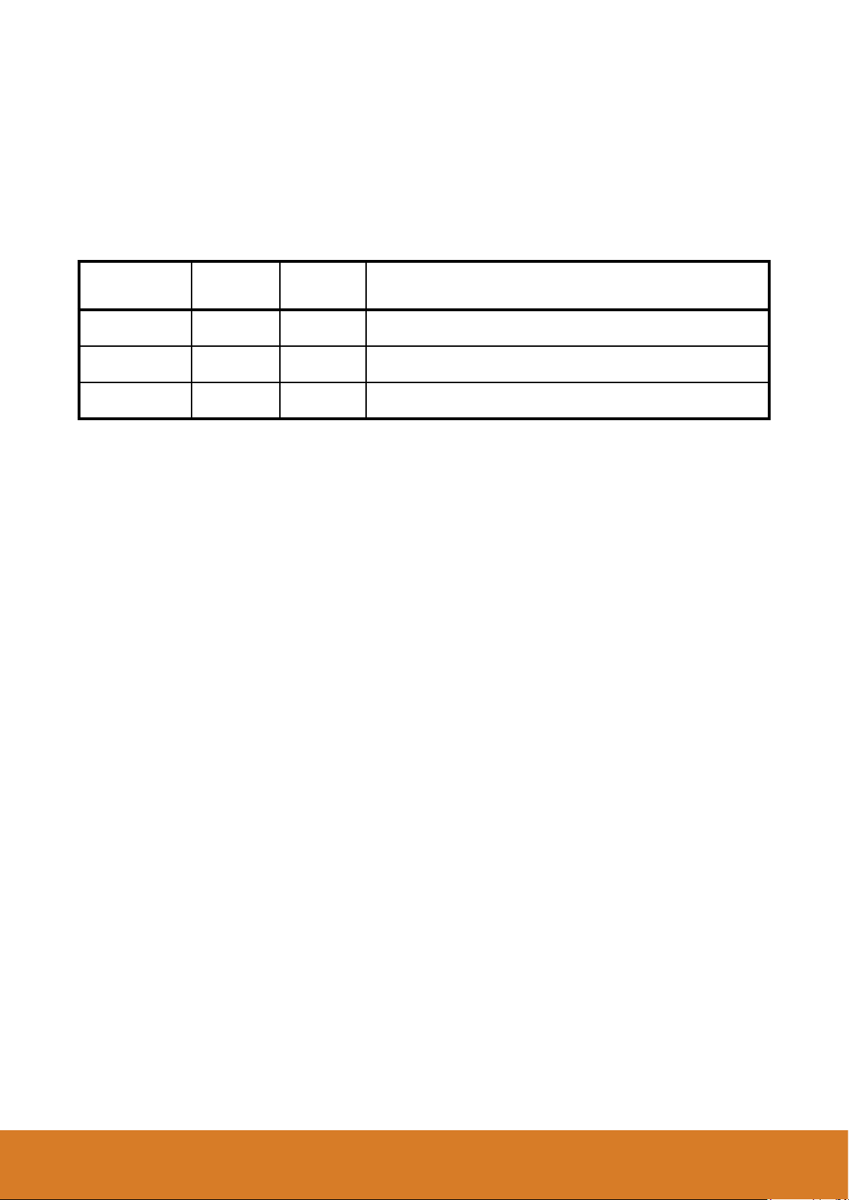
3T Method Explained
The “3T” or “through the trapdoor” method is one of the two permitted ways of assembling a tower
without the assembler being at risk of falling. This tower is a 3T tower.
As each new level of platform is installed, the operative
takes up a working position in the trap door of the
platform, standing on the ladder and leaning back
against the edge of the trapdoor aperture.
From this position clip on the 2 brace panels in the
appropriate positions. Once both are fully installed the
platform is now safe to stand on. This process ensures
operatives can fully assemble the tower without
standing on unguarded platforms.
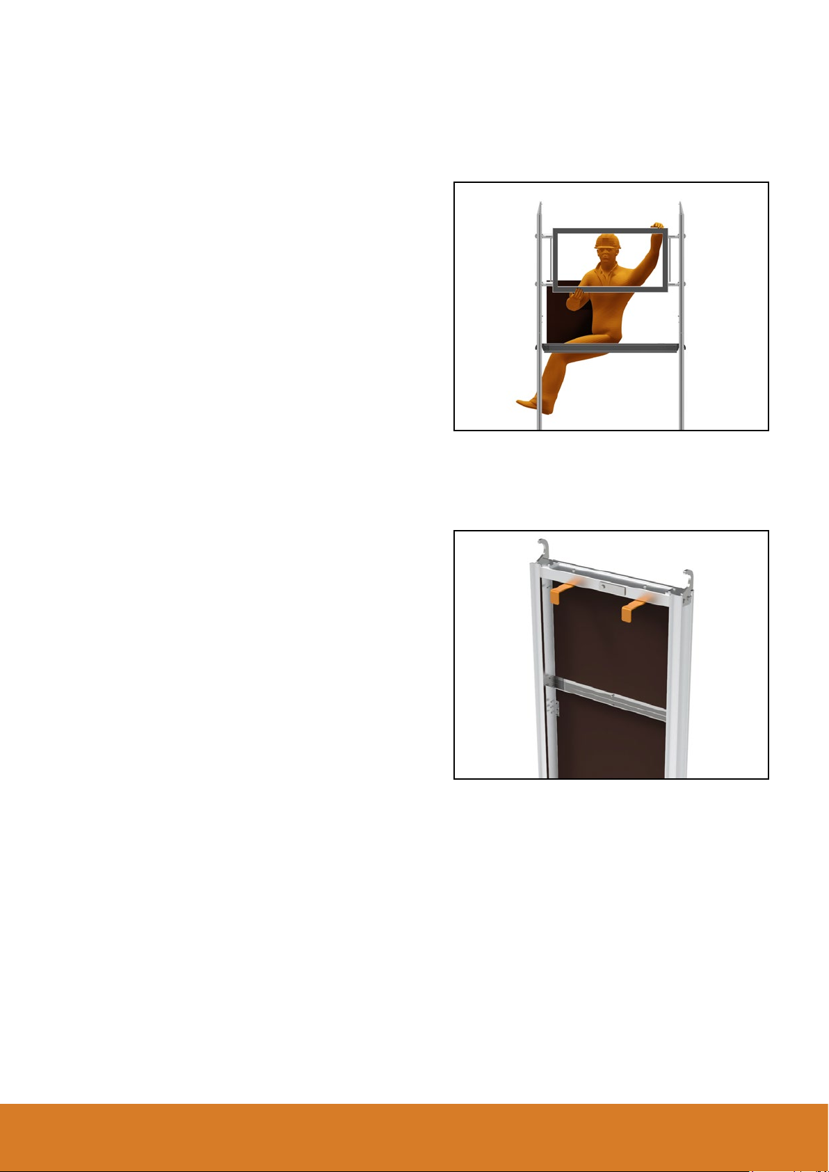
Platforms
The Mini Tower platform units have 2 angled plates
located on one end of the framework - on the underside.
During the assembly phase these plates can be rotated
outwards to enable the platform to be hooked onto the
tower structure - either on the rungs of the end frames
or onto the brace panels on the side of the tower.

Page 8ALTO Mini Tower |Assembly Guide
Component Schedule
WORKING PLATFORM HEIGHT
CODE PART DESCRIPTION 2.2 3.2 4.2
2239 125mm Dia. Castor Wheel 444
3520 Mini Tower Adj. Alum Leg (black collar) 444
3201 Mini Tower Base Frame 111
3202 Mini Tower Main Frame 468
3203 Mini Tower Brace Panel 356
3204 Mini Tower Platform 122
3205 Mini Tower Toeboard 111
3510 1.2m Horizontal Brace (Red) 111
3207 Mini Tower Stabiliser 444
3206 Component hanger frame 122
WORKING PLATFORM HEIGHT 2.2m 3.2m 4.2m
MAX. WORKING HEIGHT 4.2m 5.2m 6.2m
OVERALL TOWER HEIGHT 3.4m 4.4m 5.4m
TOTAL SELF WEIGHT OF TOWER (kg) 90 kg 122 kg 134 kg

Page 9ALTO Access Products |Lakeside Industries Ltd
2239 - 125mm castor wheel
3520 - Adj. Leg
3201 - Mini Tower Base Frame 3202 - Mini Tower Main Frame
3203 - Mini Tower Brace Panel 3204 - Mini Tower Platform 3205 - Mini Tower Toeboard
3510 - 1.2m Horiz. Brace (Red) 3207 - Mini Tower Stabiliser 3206 - Component Hanger
Frame
Components

Page 10 ALTO Mini Tower |Assembly Guide
Step 1
Insert the leg & castor assembly into
each leg of the base frame assembly
When fully inserted, ensure the
spring-loaded pin is engaged into
the hole in the side of the frames.
Ensure all 4 wheels have the brakes
applied.
Step 2
Unfold the base frame and ensure
that the gate frame latches securely.
Connect one horizontal brace to the
bottom rung on the open side of
the base frame. Make sure that the
brace is connected with the brace
hook facing downwards
Step 3
Fit a platform to the 2nd rung down.
Using a spirit level, ensure that the
framework is completely level by
adjusting the legs. Twist the serrated
collar above the wheel to adjust the
leg up & down.
ASSEMBLY INSTRUCTIONS - All Platform Working Heights
Table of contents
Other Lakeside Construction Equipment manuals


