HULTDINS SuperGrip SG User manual
Installation manual
SuperGrip SG

2017– HULTDIN SYSTEM AB.
This publication applies to the following models:
SG 260/-R S/N 026-5050 and up
SG 260S S/N 044-0280 and up
SG 360/-R/-S S/N 027-4460 and up
SG 420/-R S/N 028-2530 and up
SG 520/-R/-S S/N 029-1770 and up
SG 720S S/N 072-0001 and up
This publication contains instructions for the installation and handling of the SuperGrip SG grapples. The instructions cover
both general information for all models, and procedures or specifications applicable to individual models. If doubt should
arise concerning the validity of the instructions please consult the nearest dealer for more detailed information.
Illustrations, technical information and specifications were, as far as we have been able to judge, correct at the time of print.
However, we reserve the right to, without prior notice, revise specifications, instructions, equipment, etc. as a result of
ongoing product improvement activities.
No part of this publication may without approval of HULTDIN SYSTEM AB be translated, reproduced, stored or
transmitted electronically, mechanically, photographically or in another way not specified here.
Even if all conceivable measures have been taken to make the contents as complete as possible, HULTDIN SYSTEM AB
takes no responsibility for possible damages that may arise as a result of the instructions not being followed or improper use
of the product.
Important!
The parts and components used in HULTDIN SYSTEM AB’s products are specifically chosen. Therefore original
spare parts are always the best alternative in a possible need of repairs or upgrading.
All service and repairs should be carried out by qualified service personnel or an authorized repair shop with suitable tools
and lifting devices.
This publication is published by: HULTDIN SYSTEM AB
Skolgatan 12
Se-930 70 Malå
SWEDEN

en_sgTOC.fm contents
CONTENTS
Contents Page Contents Page
Safety instructions.................................................... 4
General safety....................................................... 4
Meaning of safety messages................................. 4
Operational Safety................................................ 5
Maintenance safety............................................... 6
Welding........................................................... 6
Modifying the equipment............................... 6
Main parts ................................................................ 7
Product description.................................................. 8
Labeling................................................................ 8
Technical data........................................................... 9
SuperGrip SG....................................................... 9
Special tools.................................................... 9
SG....................................................................... 11
SG -R.................................................................. 12
SG -S.................................................................. 13
Functional description........................................... 14
Installation.............................................................. 15
Installing the rotator........................................... 15
Maintenance instructions...................................... 16
Regular maintenance.......................................... 16
Daily maintenance........................................ 16
Every 250 hours of operation....................... 16
Lubrication ................................................... 17
Fastener joints and hydraulic hoses.............. 17
The first month of operation .............................. 17
Fasteners....................................................... 17
SAFETY INSTRUCTIONS
4 Safety instructions En011501_sg.fm
Safety instructions
General safety
• This page describes important safety instructions,
which the operator should have a good
knowledge of before the equipment is used.
• This product should only be used by operators
with proper knowledge and training.
• The owner and the operator are responsible for
following all safety regulations and that the
machine is safely equipped.
• The owner and the operator are responsible for
following National and local laws, regulations
and other instructions when using the product.
• The owner and the operator are responsible for
replacing damaged parts and/or unreadable
warning signs.
• The manual should be available at all times so
that the operator is able to follow safety
regulations and the procedures of maintenance
activities.
Meaning of safety messages
Danger!
Danger indicates a hazard with a high level of risk
which, if not avoided, will result in death, serious
injury and/or serious property damage.
Warning!
Warning indicates a hazard with a medium level of
risk which, if not avoided, could result in death,
serious injury and/or serious property damage.
Caution!
Caution indicates a hazard with a low level of risk
which, if not avoided, could result in minor or
moderate injury and/or property damage
SAFETY INSTRUCTIONS
En011501_sg.fm Safety instructions 5
Operational Safety
• Check the grapple for damages at the beginning
of each shift. Tighten all fasteners regularly.
• Make sure that the hydraulic pressure in the
grapple cylinder is adjusted according to the
specifications. If the pressure is too low the
grapple will not be able to carry its load. If the
pressure is too high, the grapple will be
overloaded, which could cause a structural
failure, resulting in injury and/or property
damage.
• The grapple must not be used for lifting
personnel.
• The grapple is not designed for handling rocks,
heavy spare parts, etc.
• The grapple arms on the SuperGrip II-A must
NOT be used to dig up stumps and rocks.
If used as described above the grapple arms or other
parts of the grapple could fail, resulting in injury and/
or property damage.
• The load of the grapple must not exceed the
recommended maximum rating as structural
failure could occur, resulting in injury and/or
property damage.
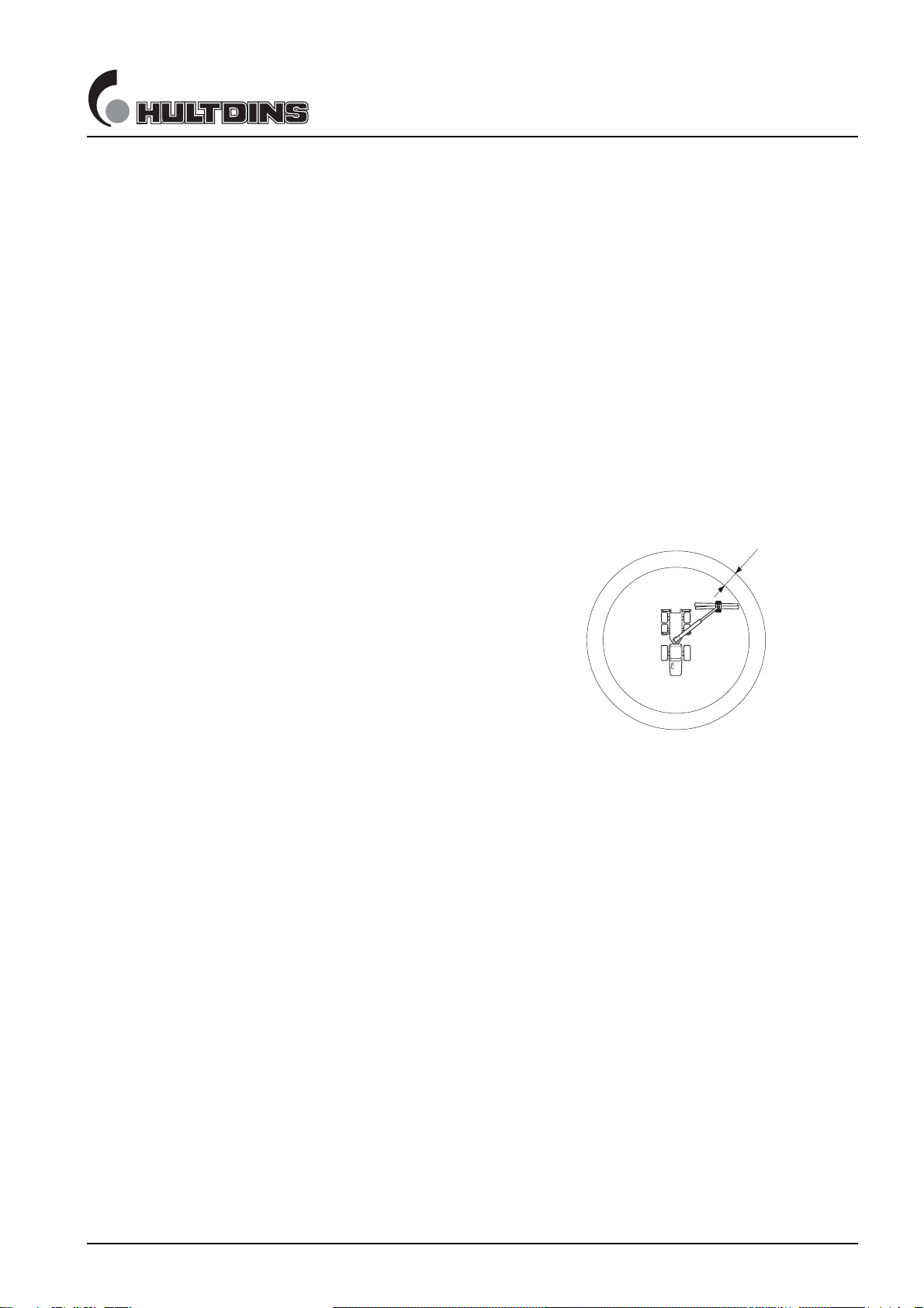
• When operating this equipment ensure all
unauthorized persons remain at least 15 meters
clear of the machine.
• The operator must immediately evict
unauthorized persons who are in the danger zone
or are heading towards the danger zone
• Personnel inside the danger zone must be well
protected against falling load.
• Personnel inside the danger zone must keep clear
of hanging load.
• The operator should be aware that the load, or
parts of the load, could fall from the grapple at
any time.
15 meter
SAFETY INSTRUCTIONS
6 Safety instructions En011501_sg.fm
Maintenance safety
• The machine's condition must be checked
regularly, daily inspections shall be performed
and any deficiencies must be corrected. The
machine shall be maintained in such condition
that the operator or other persons not exposed to
danger or accidents.
• Never commit any service on the equipment
without proper knowledge. All service and
repairs in electrical and hydaulical systems
should be carried out by qualified personnel only.
• Repair any damages immediate when discovered.
Do not use the equipment until any damages are
rectified.
• Before performing any maintenance or service
work, lower the grapple to the ground and shut
off the engine. Turn off any master shut-offs and
do not allow personnel in the cab.
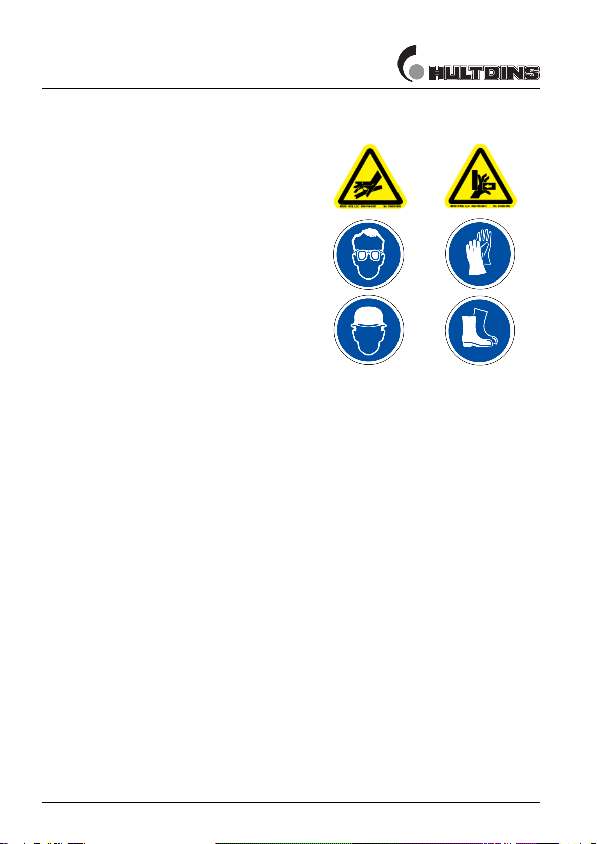
• Use safety glasses and protective gloves when
servicing the equipment. Hydraulic oil or
lubricants in contact with skin or eyes may cause
irritations or allergies.
• Use hard hat and safety boots when servicing the
equipment. Leakage of hydraulic oil or lubricants
will increase the risk of slipping or falling.
• The grapple has sharp edges. Use proper
wrenches and protective gloves when working on
the grapple
• Hydraulic hoses and adapters may be pressurized
even with the engine shut off. Loosen any parts
with caution.
• Always make sure that the system is
depressurized before committing any service on
the equipment.
• Always secure movable parts mechanically
before any hydraulic hose is loosened.
• Never try to stop a leakage in the hydraulic
system with you hand. Pressurized hydraulic oil
can be injected under the skin and cause death or
severe damage.
Welding
In case of a structural repair of the equipment, when
welding may be needed, consult the dealer for
recommended instructions.
When welding on the grapple the following steps must
be taken:
• Make sure that fire-extinguishing equipment is
available.
• Clean the area around the welding area to
eliminate any fire hazard.
• Connect the ground wire so the welding current
does not pass over any bushings.
• Place the ground wire as closeto the welding area
as possible.
• When welding close to bushings, dissassemble
the bushings asthey are made of a plastic
compound-material which high temperatures may
damage.
Modifying the equipment
It is not approved to:
• Modify the grapple without the consent of
HULTDIN SYSTEM AB.
• Alter the function of the grapple without the
consent of HULTDIN SYSTEM AB.
• Use spare parts other than original HULTDINS
parts.
MAIN PARTS
en011502_sg.fm SuperGrip SG 7
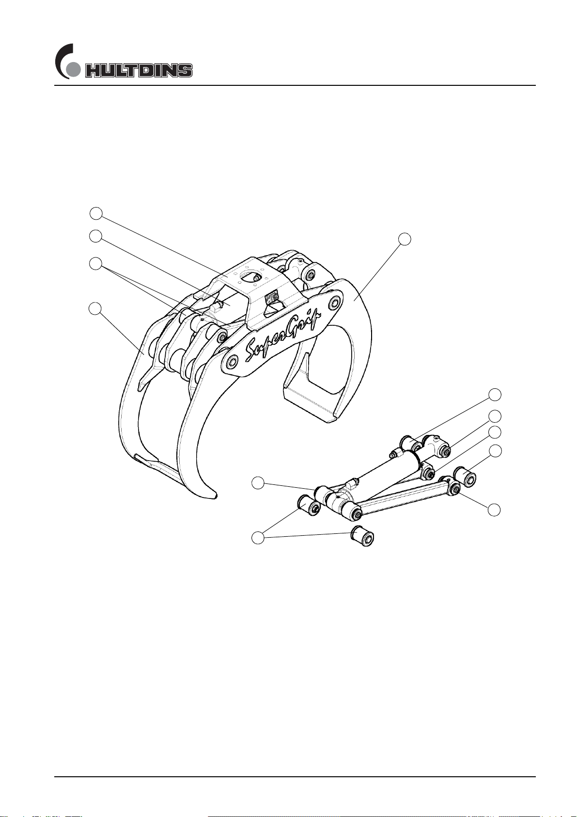
Main parts
The SuperGrip SG is made up of the following main parts.
All parts are replaceable.
Fig. 1 Main parts
1
2
3
4
10
6
7
8
9
5
5
9
1 Frame
2 Female grapple arm
3 Male grapple arm
4 Pin-joint system, frame-female grapple arm
5 Pin-joint system, frame-male grapple arm
6Rod
7 Hydraulic cylinder
8 Pin-joint system, grapple arm-rod-hydraulic cylinder
9 Drill holes for rotator bracket
10 Pin-joint system, rod-male grapple arm
11 Pin-joint system, piston rod-male grapple arm
PRODUCT DESCRIPTION
8 SuperGrip SG en011503_sg.fm
Product description
The SuperGrip SG is a short wood grapple that is
generally mounted on cranes/booms intended for on road-
and off road-vehicles. The SuperGrip SG is only intended
to be used for timber, cut-to-length, whole-tree and waste
wood systems.
The SuperGrip SG must not be used when lifting rocks or
when performing equivalent lifts as there is a risk that the
grapple arms or other parts of the grapple may fail, which
could result in injury or damaged equipment.
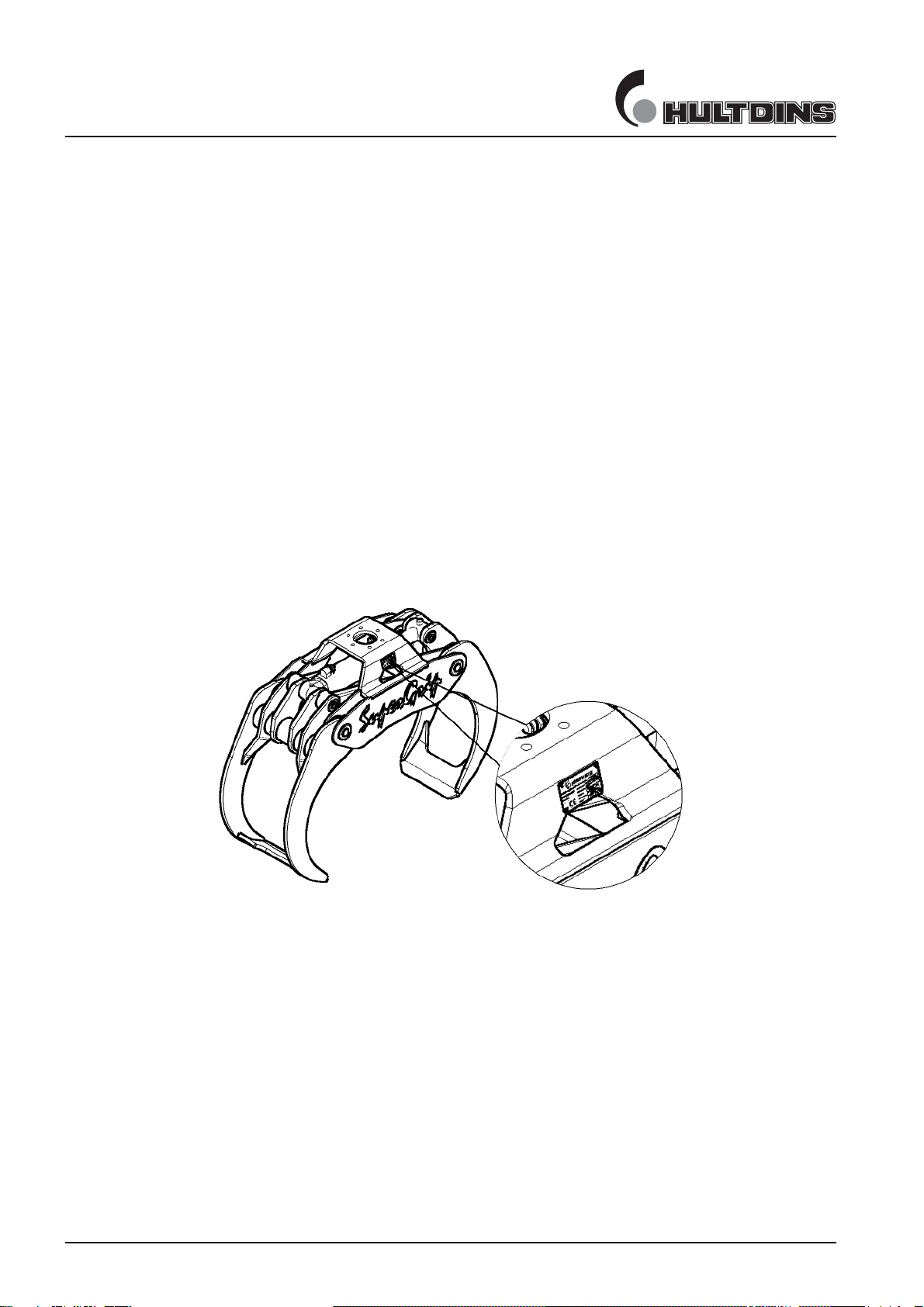
Labeling
The SuperGrip SG is labeled with serial number, model
number, max. load, max.pressure and a CE-label
according to the following figure.
Fig. 2 Labeling
TECHNICAL DATA
en011504_sg.fm SuperGrip SG 9
Technical data
SuperGrip SG
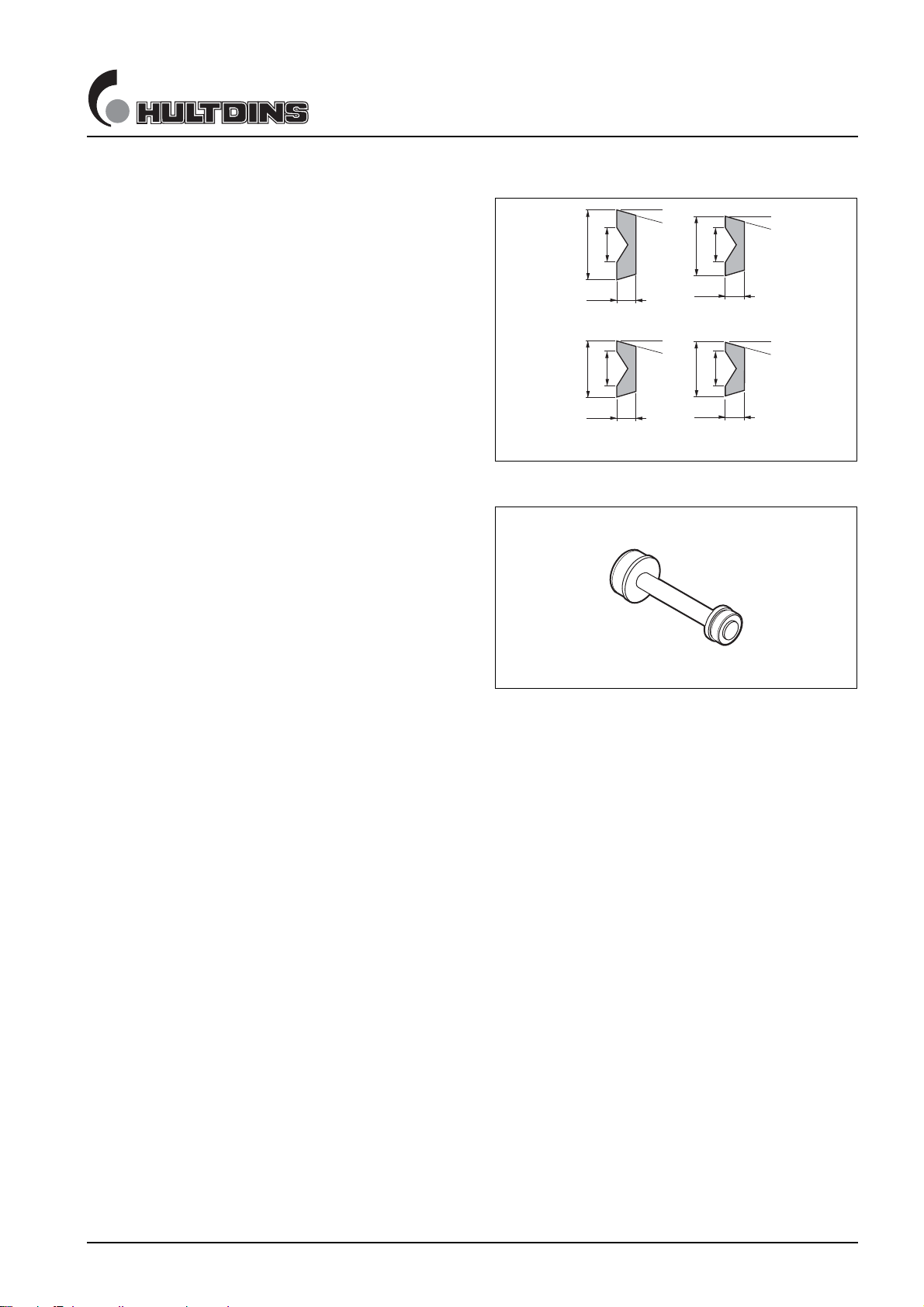
Special tools
Description Diam. Order No.
Mandrel, pin-joint system......... 50 mm 0660 207
60 mm 0683 010
70 mm 0660 208
80 mm 0683 011
Mandrel, bushings..................... 50 mm 0660 290
60 mm 0683 150
70 mm 0660 290
80 mm 0683 150
Fig. 3 Mandrel, Pin-joint system
Ø70
Borr Ø30
15
15°
Ø60
Borr Ø30
15
15°
Ø55
Borr Ø30
15
15°
Ø45
Borr Ø30
15
15°
Ø80 Ø70
Ø60 Ø50
Fig. 4 Mandrel, bushings
Grease and Loc-Tite
Grease Use a mineral oil based grease thickened with, or mixable with a lithium soap.
The grease should be classified as L-XCCIB2 according to ISO 6743-9.
Molybdendisulfid content max 3 %. Base fluid viscosity 170 to 220 cSt at
40°C. NLGI class 1-2.
Greasing intervals
Every 1000 hours of use.
Hydraulic hoses
The cylinder hoses should be 1/2” (13,0 mm) according to DIN 20022; SAE 100 R2AT rating. Hose
assemblies should be sized for burst pressure with at least a triple safety factor (three times the working
pressure).
Rotator fasteners
The rotatorn should be installed to the grapple with fasteners with the dimension M16 of grade min.
10.9, alternativ M20 of grade min. 8.8
TECHNICAL DATA
10 SuperGrip SG en011504_sg.fm
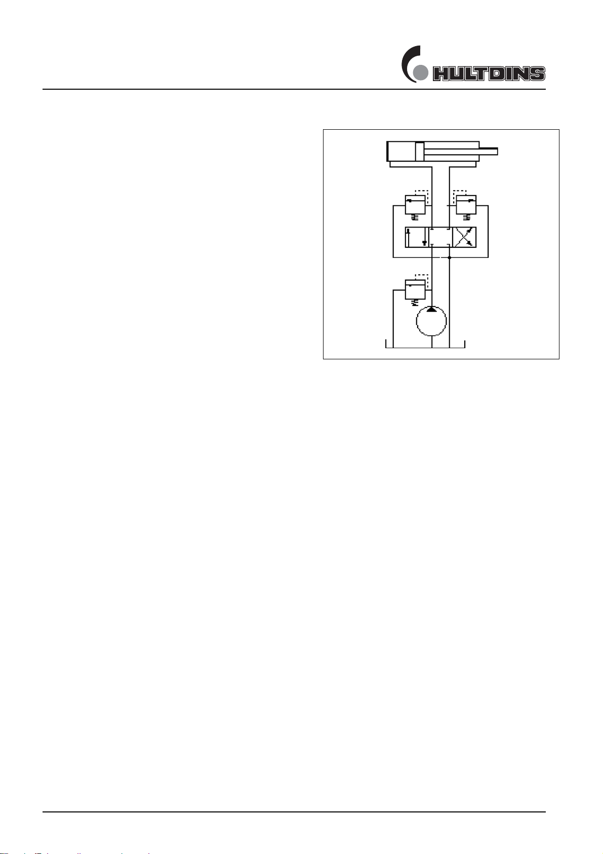
Operating pressure
Max. operating pressure ..... 25 MPa
Fig. 5 Hydraulic diagram
Torque and socket/wrench sizes
Torque Socket/wrench size
MC6S 16 12.9 ......... 330 Nm 14 mm
M6S 20 10.9 ......... 500 Nm 30 mm
MC6S 20 12.9 ......... 500 Nm 17 mm
M6S 24 10.9 ......... 900 Nm 36 mm
Piston ø80............................ 700 Nm -
Piston ø90/ø100 850 Nm -
Gland ø80............................ 700 Nm -
Gland ø90/ø100................... 850 Nm -
Table of contents
Other HULTDINS Construction Equipment manuals


