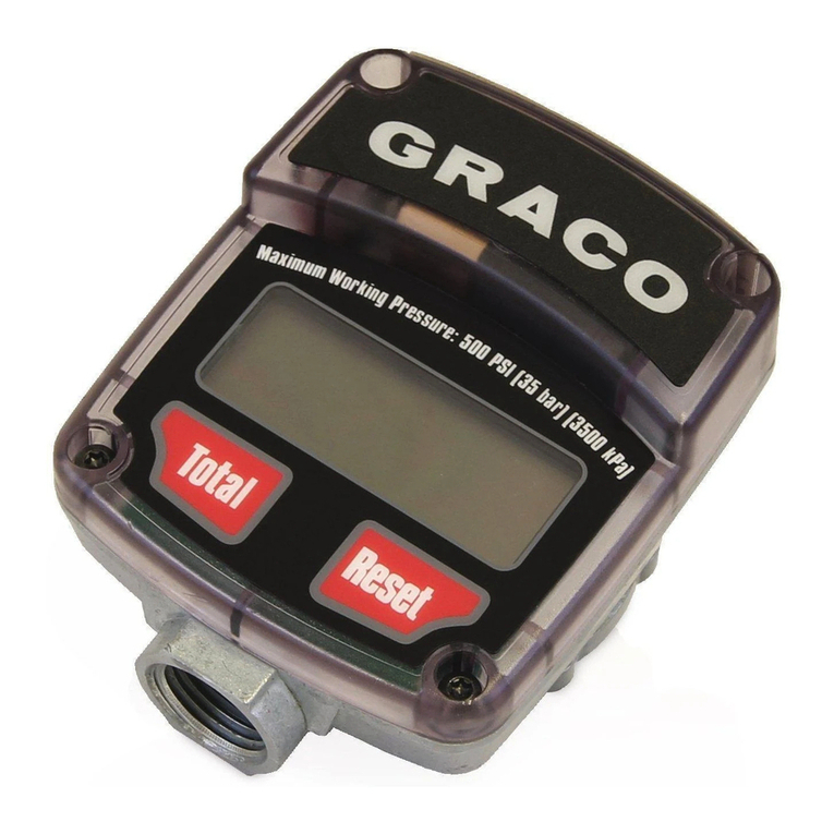
Graco 26C266 User manual

3A6715B
EN
Accessory
Haz Loc Wireless
Remote & Meter /
Solenoid Barriers
Components that allow the installation of a ProDispense™ user-interface and fluid control
in a hazardous location. For professional use only.
26C266
Hazardous Location Wireless Remote
25E765
Meter Barrier Enclosure Assembly
25B223
Solenoid and Meter Barrier Enclosure Assembly, with
Solenoid
Important Safety Instructions
Read all warnings and instructions in this
manual and in your dispensing
operations manual before using the
equipment. Save these instructions.
Hazardous Location Wireless Remote
Barrier Enclosure Assembly

Related Manuals
2 3A6715B
Contents
Related Manuals . . . . . . . . . . . . . . . . . . . . . . . . . . . 2
Overview . . . . . . . . . . . . . . . . . . . . . . . . . . . . . . . . . . 3
Barrier Enclosure . . . . . . . . . . . . . . . . . . . . . . . . 3
Meter Barrier Assembly (25E765) . . . . . . . . 3
Meter and Solenoid Barrier Assembly
(25B223) . . . . . . . . . . . . . . . . . . . . . . . . 3
Wireless Remote Network . . . . . . . . . . . . . . . . . 3
ProDispense and Wireless Nodes . . . . . . . . 3
Gateway . . . . . . . . . . . . . . . . . . . . . . . . . . . . 3
Remote Operator Station with LED Indicator 3
Barrier Enclosure . . . . . . . . . . . . . . . . . . . . . . . . . . 4
Barrier Enclosure Assemblies . . . . . . . . . . . . . . . 4
Barrier Enclosure Component Entity
Parameter Data . . . . . . . . . . . . . . . . . . . 5
Barrier Enclosure Approvals . . . . . . . . . . . . . 5
Barrier Enclosure Installation . . . . . . . . . . . . . . . 6
Grounding . . . . . . . . . . . . . . . . . . . . . . . . . . . 6
Typical Barrier Enclosure Installation . . . . . . 7
Barrier Enclosure Wiring Diagram . . . . . . . . 7
Barrier Enclosure Control Drawing (25E765
and 25B223) . . . . . . . . . . . . . . . . . . . . . . 8
26C266 Wireless Remote . . . . . . . . . . . . . . . . . . . . 9
26C266 Wireless Remote Components . . . . . . . 9
26C266 Wireless Remote Approvals . . . . . 10
Wireless Remote Kit Installation . . . . . . . . . . . . 11
Grounding . . . . . . . . . . . . . . . . . . . . . . . . . . 11
Typical Installation . . . . . . . . . . . . . . . . . . . 12
26C266 Wireless Electrical Schematics . . . 13
26C266 Wireless Control Drawing . . . . . . . 14
26C266 Kit Component Identification . . . . . 15
Gateway Component Identification . . . . . . . 16
26C266 Kit Mounting Instructions . . . . . . . . 16
Cable Connections . . . . . . . . . . . . . . . . . . . 17
Set Up Wireless Network . . . . . . . . . . . . . . . . . 18
Bind Nodes To Form Network . . . . . . . . . . . . . . 18
Gateway LED Behavior . . . . . . . . . . . . . . . . 18
Node LED Behavior . . . . . . . . . . . . . . . . . . 18
Operation . . . . . . . . . . . . . . . . . . . . . . . . . . . . . . 19
Test the Remote Operator Station and Node 19
Remote Operator Station Functions and
Indicators . . . . . . . . . . . . . . . . . . . . . . . 19
Troubleshooting . . . . . . . . . . . . . . . . . . . . . . . . . . . 20
Common Troubleshooting Issues . . . . . . . . . . . 20
LED Message Codes . . . . . . . . . . . . . . . . . . . . . 21
LCD Message Codes . . . . . . . . . . . . . . . . . . . . 23
Repair . . . . . . . . . . . . . . . . . . . . . . . . . . . . . . . . . . . 24
Battery Replacement . . . . . . . . . . . . . . . . . . . . . 24
Battery Disposal . . . . . . . . . . . . . . . . . . . . . . . . 24
Barrier Replacement . . . . . . . . . . . . . . . . . . . . . 24
Parts . . . . . . . . . . . . . . . . . . . . . . . . . . . . . . . . . . . . 25
Barrier Enclosure Assembly . . . . . . . . . . . . . . . 25
26C266 Hazardous Location Wireless Remote . 26
Dimensions . . . . . . . . . . . . . . . . . . . . . . . . . . . . . . . 27
Barrier Enclosure . . . . . . . . . . . . . . . . . . . . . . . . 27
Gateway . . . . . . . . . . . . . . . . . . . . . . . . . . . . . . 28
Node . . . . . . . . . . . . . . . . . . . . . . . . . . . . . . . . . 28
Remote Control and Indicator Enclosure . . . . . . 29
Appendix A - Factory Settings . . . . . . . . . . . . . . . 30
User Configuration Tool . . . . . . . . . . . . . . . . . . . 30
Appendix B - Conducting a Site Survey . . . . . . . 31
Site Survey Using the Menu System . . . . . . . . . 31
Site Survey from a Gateway Board Model . . . . 31
Improving Site Survey Results . . . . . . . . . . . . . 32
Performance Levels . . . . . . . . . . . . . . . . . . 32
Technical Specifications . . . . . . . . . . . . . . . . . . . . 33
FCC / IC Notice
26C266 Assembly (17V930 and 17V933
models) . . . . . . . . . . . . . . . . . . . . . . . . . . . . 33
Graco Standard Warranty . . . . . . . . . . . . . . . . . . . 34
Related Manuals
Manual Description
3A3469 ProDispense™, Operation/Parts
308778 Volumetric Fluid Flow Meter,
Instructions/Parts
— — — Banner Manual; included with product

Overview
3A6715B 3
Overview
The barrier enclosure assemblies and wireless remote
network are intended to be used exclusively with a
Graco ProDispense system.
Barrier Enclosure
The barrier enclosure assemblies (25E765 and 25B223)
use R. STAHL’s safety barrier technology for field
devices.
Meter Barrier Assembly (25E765)
The meter barrier assembly includes an enclosure, with
cover; DIN rail-mounted barrier; panel-mounted
connector; and 50 ft. cable to route from the enclosure
assembly to the meter located in the hazardous
location.
This assembly includes connectors on the enclosure
and meter cable for direct and convenient connection to
a Graco meter sensor. The included barrier has
matching entity parameters to the Graco meter sensor.
The meter sensor, when used with this barrier, is
approved for installation and use in a Class I, Div 1, or
Class I, Zone 0 hazardous location. See Barrier
Enclosure Component Entity Parameter Data and
Barrier Enclosure Approvals, on page 5, for specific
classification details.
Meter and Solenoid Barrier Assembly
(25B223)
The meter and solenoid barrier assembly includes all
components of the 25E765 assembly. It also includes a
DIN rail-mounted solenoid barrier; 36 in. of input cable;
an additional 50 ft. of safe-side cable to route to the
solenoid mounted in the hazardous location; strain-relief
fittings at the enclosure for cable management; a 24
VDC Class I, Div 1 solenoid valve (MAC 411 valve) with
fittings and wire splices.
NOTE: The MAC 411 valve is approved for North
American Class I, Div 1 installations only.
Wireless Remote Network
The 26C266 Hazardous Location Wireless Remote
allows for limited operation of a ProDispense from a
user-interface located in a hazardous location. It uses
Banner Engineering’s FlexPower® power management
technology to operate wireless nodes (1), remotes
(sensors) (3), and gateways (4). See 26C266 Kit
Component Identification on page 15.
ProDispense and Wireless Nodes
• The ProDispense ADM (Advanced Display Module)
must have software revision 1.03.007, or higher,
installed. Refer to the ADM software update
procedure in your ProDispense operation manual.
• The wireless nodes (1) have been pre-configured
for proper functionality between the nodes and the
ProDispense.
- The modes and dip switch settings have been
pre-set.
- Cable wiring to terminal blocks has been
completed to eliminate in-field wiring. The I/O
and wireless functionality are tested prior to
shipping.
- All field connections are plug-in cable
connectors. See Cable Connections on
page 17.
Gateway
The gateway (4) must be connected to an FCM (fluid
control module) fluid panel and the primary FCM
communicating with that panel.
• Only recipes, which are normally controlled by the
control panel, can be dispensed using the remote
operator station (3). See FIG. 7.
• The fluid panel to which the gateway (4) is
physically connected must manage a fluid included
in all recipes to be dispensed.
Remote Operator Station with LED
Indicator
The remote operator station and LED indicator (3) is
connected by a conductor cable (2) to a wireless
node (1).

Barrier Enclosure
4 3A6715B
Barrier Enclosure
Barrier Enclosure Assemblies
NOTE: The barriers and MAC valve have matching entity parameters.
Assembly Component Description
25E765 -
Meter Barrier
Enclosure
Assembly
111985 -
Dual-channel Stahl
Barrier
Provides power and signal interface to the Graco G3000 meter sensor.
17C888 -
50 ft Meter Cable
Pre-wired to the barrier, using individually-shielded twisted-pair cables
selected to be used in hazardous locations.
19A758 -
Barrier Enclosure
Metal enclosure with hinged cover, for barrier mounting and protection.
The barrier is DIN-rail mounted in the enclosure, and cable connections
are separated by entering the enclosure on opposite ends of the barrier.
The cables are secured to maintain separation by strain relief cable
grommets and adhesive wire-conductor anchoring pads.
25B223 -
Solenoid and
Meter Barrier
Enclosure
Assembly, with
Solenoid
111985 -
Dual-channel Stahl
Barrier
Same as for 25E765, Meter Barrier Enclosure Assembly.
514895 -
Single-channel Stahl
Barrier
Additional single-channel barrier for a solenoid valve circuit.
19A982 -
IS-approved MAC 411
Series 2/5 Solenoid
Valve
Assembly includes pneumatic inlet and outlet fittings, and sintered
exhaust silencers.
Solenoid Barrier Cables Shielded single-twisted-pair cables, secured to maintain separation by
strain relief cable grommets and adhesive wire-conductor anchoring
pads. The solenoid cables are spliced with Wago lever-lock connectors.
19A758 -
Barrier Enclosure
Same as for 25E765, Meter Barrier Enclosure Assembly.

Barrier Enclosure
3A6715B 5
Barrier Enclosure Component Entity Parameter Data
Entity parameter data can be found on the component’s label. The 111985 Meter Barrier is common to both barrier
enclosure assemblies. The 514895 Solenoid Barrier is only included in the 25B223 Solenoid Barrier and Solenoid
Enclosure Assembly.
Barrier Enclosure Approvals
Meter Circuit
Class I, Division 1, Group C,D T3
111985
Barrier
G3000
Meter Sensor
Uo = 28 V Ui = 30 V
Io = 107 mA Ii = 110 mA
Po = 749 mW Pi = 800 mW
Co = 9.6 mH Ci = 0.4 µF
Lo = 0.65 µH Li = 0.01 µH
Solenoid Circuit
514895
Barrier
19A982
Solenoid Valve
Uo = 28 V Ui = 30 V
Io = 100 mA Ii = 175 mA
Po = 700 mW Pi = N/A
Co = 11mH Ci = 0 µF
Lo = 0.65 µH Li = 0 µH
2 I G
Ex ia IIB T3
Part No. Description Approvals
25E765 Meter Barrier Enclosure Assembly Barriers are approved through R. Stahl, Inc.
Barrier (p/n 111985) is approved to Class I, Div 1, Group D
T3, and Class I Zone 0; 2 I G Ex (ia Ga) IIB/IIC T4 Gc.
Sensors (G3000 Sensors only; p/n 24W650 or 24W651)
are approved through Graco. Class I, Div 1, Group D T3,
and Class I, Zone 0; 2 I G Ex ia IIA T3.
Entity parameters of the barrier and Graco meter sensor
have been matched for proper connection and safe use.
25B223 Solenoid and Meter Barrier Enclosure
Assembly, with Solenoid
Barriers are approved through R. Stahl, Inc.
Barriers (p/n 514895) are approved to Class I, Div 1, Group
D T3, and Class I Zone 0; 2 I G Ex (ia Ga) IIB/IIC T4
Gc.
Solenoids (p/n 19A982) are approved through MAC
Engineering to Class I, Div 1, Group A, B, C, D, E, F, G,
0-50°C.
Entity parameters of the barrier and Graco solenoid valve
have been matched for proper connection and use.
UL 698A
CSA C22.2 no.286
UL 698A
CSA C22.2 no.286

Barrier Enclosure
6 3A6715B
Barrier Enclosure Installation
With the Barrier Enclosure Assemblies (8) installed, it is
possible to move key components from the
ProDispense Fluid Panel (12) in the non-hazardous
location and to safely install them at the dispensing
station in the hazardous location. These include the
Fluid Flow Meter (10) and the Dispense Valve (13). See
FIG. 1 and FIG. 2 on page 7.
NOTE: Do not use the solenoid valve provided with the
ProDispense Fluid Panel (12) in hazardous locations.
Only use the new Solenoid Valve (9) provided with the
Barrier Enclosure Assembly (8).
An approved Solenoid Valve (9) and a Fluid Flow
Meter (10) must both be used with a Barrier Enclosure
Assembly (8) when installed in a hazardous location.
Grounding
Barrier Enclosures (8): Connect the other end of the
factory-installed ground wire (14) to a true earth ground
using the screw clamp provided. See FIG. 1 on page 7.
Check the resistance between each barrier enclosure
and true earth ground. If the resistance is 1 ohm or
greater, a different ground site may be required. Do not
operate the system until the problem has been
corrected.
ProDispense Fluid Panels (12): Ground as instructed
in the ProDispense operations manual (3A3469).
Solenoid Valve (9): Must be mounted to a grounded
support structure when moved from the panel into a
hazardous location.
Fluid Flow Meter (10): Must be mounted to a grounded
support structure when moved from the panel into a
hazardous location.
Dispense Valve (13): Must be mounted to a grounded
support structure when moved from the panel into a
hazardous location.
WARNING
FIRE AND EXPLOSION HAZARD
Do not substitute or modify system components as
this may impair intrinsic safety. Do not install
equipment approved only for a non-hazardous
location in a hazardous location.
STATIC SHOCK HAZARD
Improper grounding, setup, or usage of the system
can cause static shock. To prevent shock:
• Turn off and disconnect power at main switch
before disconnecting any cables and before
installing equipment.
• Connect only to grounded power source.
• All electrical wiring must be done by a qualified
electrician and comply with all local codes and
regulations.
WARNING
This equipment must be grounded to reduce the risk
of static sparking and electric shock. Electric or static
sparking can cause fumes to ignite or explode.
Improper grounding can cause electric shock.
Grounding provides an escape wire for the electric
current.

Barrier Enclosure
3A6715B 7
Typical Barrier Enclosure Installation
This is an example of how the barrier assembly kits could be integrated into a ProDispense setup. ProDispense
component installation is covered in manual 3A3469.
Barrier Enclosure Assembly Key:
8 Barrier Enclosure Assembly
ProDispense Key:
9 Solenoid Valve†‡
10 Fluid Flow Meter*†
11 ProDispense Control Panel
12 ProDispense Fluid Panel
13 Dispense Valve*
14 Ground Wire (24 ft, factory-installed)
* Removed from Fluid Panel when installed in hazardous
locations; mounting hardware not included.
† Must be used with a Barrier Enclosure Assembly and
approved Solenoid Valve when installed in a hazardous
location.
‡ Do not use the Solenoid Valve provided with the ProDis-
pense Fluid Panel.
Barrier Enclosure Wiring Diagram
FIG. 1 Typical Installation with Hazardous Location Solenoid and Meter Barriers
Non-Hazardous Location Hazardous Location
8
89†‡
10*†
12
12
11 13*
14
FIG. 2 Barrier Enclosure Wiring Diagram
RED
WHITE
BLACK
111985
BARRIER
3
4
1
2
GND.
SCREW
GND.
SCREW
514895
BARRIER
3
4
1
2
GND.
SCREW
GND.
SCREW
METER CABLE
BLUE
WHITE
SHIELD
BLUE
50 FT.
50 FT.
WHITE
SHIELD
CAGE CLAMP
CONNECTOR
SOLENOID OUTPUT
CABLE
RED
BLACK
SOLENOID VALVE
19A982 MAC IS
411 SERIES
CONNECTS TO
GRACO METER
SENSOR
24W650/24W651
BLUE
WHITE
SHIELD
RED
WHITE
BLACK
RED
WHITE
BLACK
3
1
2
1K
PANEL MOUNT CONNECTOR
ENCLOSURE
9, SIGNAL
8, COMMON
BLUE
WHITE
SHIELD
TERMINAL
BLOCK
PRODISPENSE FLUID PANEL
26A131 / 26A132 / 26A165
METER CABLE
JUNCTION BOX
SOLENOID INPUT
CABLE
3
1
2
Non-Hazardous Location Hazardous Location

Barrier Enclosure
8 3A6715B
Barrier Enclosure Control Drawing (25E765 and 25B223)
FIG. 3 Barrier Control Drawing
Non-Hazardous Location Hazardous Location
Barrier dual channel p/n 111985
Stahl 9002/13-280-110-001
Barrier dual channel p/n 514895
Stahl 9001/01-280-110-101
See the control drawing for each IS barrier.
Install in accordance with the National Electrical Code
(NEC) and any applicable local codes.
Meter sensor,
Graco 24W650 /
24W651.
Solenoid,
MAC 411.
Entity Parameters
Uo 28 Volts
Io 107 mA
Po 749 mW
Co 9.6 mH
Lo 0.65 µH
Entity Parameters
Uo 28 Volts
Io 100 mA
Po 700 mW
Co 11 mH
Lo 0.65 µH
Entity Parameters
Ui 30 Volts
Ii 110 mA
Pi 800 mW
Ci 0.4 µF
Li 0.01 µH
Entity Parameters
Ui 30 Volts
Ii 175 mA
Pi N/A
Ci 0 µF
Li 0 µH
Meter cable, 50 ft
p/n 19A751
Solenoid cable, 50 ft
p/n 19A948
Ex 2 I G Ex ia IIB T3
Class I, Div 1, Group C,D T3
Ex 2 I G Ex ia IIB T3
Class I, Div 1, Group C,D T3
Spring lever
wire connector
Enclosure,
conductive
GG
G
G
G
1
2
3
4
1
2
3
4
Blue
White
Red
Black
Spring lever
wire connector

26C266 Wireless Remote
3A6715B 9
26C266 Wireless Remote
26C266 Wireless Remote Components
The 26C266 wireless remote allows for limited operation of a ProDispense from a user-interface located in a
hazardous location. The kit is comprised of three major components and a conductor cable.
NOTE: The ProDispense must have software revision 1.03.007, or higher, to be functional with the 26C266 Wireless
Remote kit. A software update token is included with the kit.
Component Location Description
17V933 -
Transceiver Gateway
Non-hazardous Wireless communication gateway with discrete digital I/O conducted
through a pre-wired signal cable for interfacing with a Graco fluid
control module (FCM). Inputs include start and stop, and outputs
include dispense and alarm.
17V930 -
Transceiver Node
Hazardous Third-party approved battery-powered wireless transmitter, with a
discrete IS (intrinsically safe) I/O for interfacing with a user-interface
push-button module.
17V932 -
Remote Operator
Push-Button Station and
LED Indicator
Hazardous User-interface enclosure assembly with momentary-contact
push-button switches and an LED indicator. The LED indicator
components were selected based on third-party certifications to US,
Canada, ATEX, and IECEx standards for use in hazardous locations.
17V931 -
Conductor Cable
Hazardous Cable for IS circuit, with an IS circuit designation label. The cable has
male and female M12 connectors. The cable is used for connecting IS
circuits of the user interface indicator lights and switches to the wireless
transceiver node.

26C266 Wireless Remote
10 3A6715B
26C266 Wireless Remote Approvals
Part No. Description Approvals through Banner Engineering
17V930 Transceiver node only.
Battery-operated, with entity
parameter-approved
input/output interface, with
indicator lights and switches.
See 26C266 Wireless Control
Drawing, on page 14, for entity
parameter details.
Approvals
CSA - C/US
Class I, Division 1, Groups A, B, C, D; Class II, Division 1, Groups E, F, G;
Class III, Division 1 (Ex ia IIC T4; AEx ia IIC T4)
Certificate: 2008243
ATEX
Zone 0 (Category 1G) and 20 (Category 1D), Temperature Class T4 (II 1 GD;
Ex ia IIC T4 Ga; Ex ia IIIC T82°C Da IP68)
Certificate: LCI 08 ATEX 6098 X
Special Conditions for Safe Use Imposed by Intrinsic Safety Certificate LCIE 08
ATEX 6098 X: Ambient temperature range is -40 to 70 °C. Sure Cross® DX99
FlexPower devices can only be connected to Intrinsically Safe certified equipment or
simple apparatus as defined by EN 60079-11. All connected equipment must comply
with the Entity Parameters (Safety Parameters) listed in the Control Drawings (p/n
141513). The device must only use a lithium battery manufactured by XENO, type
XL-205F.
17V932 User interface assembly, with
IS-approved LEDs and simple
apparatus-assessed switches.
1725
1725
IEC IECx SIR 13.0020X
ATEX Sira 13ATEX2058X
CSA CoC 2679646
CSA-C/US
Gas and Vapors: Class I Zone 0 AEx/Ex ia IIC T4 Ga; Class I Div 1
Groups A, B, C, D
ATEX/IECEx
Gas and Vapors: II 1 G Ex ia IIC T4 Ga (Group IIC Zone 0)
Approvals
This manual suits for next models
2
Table of contents
Other Graco Measuring Instrument manuals
Graco
Graco EM5 Series User manual

Graco
Graco 24J318 User manual

Graco
Graco Accu-Shot 233807 Parts list manual

Graco
Graco G250 Parts list manual

Graco
Graco FX250 Operation manual

Graco
Graco Pulse TLM User manual

Graco
Graco Series D User manual

Graco
Graco IniFlex Operation manual

Graco
Graco 256282 User manual

Graco
Graco LDM5 User manual

Graco
Graco Accu-Shot 233807 User manual

Graco
Graco PD44 User manual

Graco
Graco 244075 User manual

Graco
Graco 260415 Operation manual

Graco
Graco Pulse TEK 811 Setup guide

Graco
Graco PGM Parts list manual

Graco
Graco G3000 Operation manual
Graco
Graco SDMM8 User manual

Graco
Graco HORIZON Operation manual

Graco
Graco 308287 Datasheet