Deif MIB 8000 User manual

DESIGNER'S HANDBOOK
MIB 8000
Multi-instrument
4189320063D

1. About the Designer's handbook
1.1 Document information............................................................................................................................................................................................................ 3
1.1.1 Intended users of the Designer's handbook........................................................................................................................................................... 3
1.1.2 Symbols for general notes..............................................................................................................................................................................................3
1.1.3 Symbols for hazard statements....................................................................................................................................................................................3
1.2 Warnings and safety.................................................................................................................................................................................................................4
1.3 Support information................................................................................................................................................................................................................. 5
1.4 Legal information.......................................................................................................................................................................................................................5
2. About the MIB
2.1 Product overview....................................................................................................................................................................................................................... 6
2.1.1 Application.............................................................................................................................................................................................................................6
2.1.2 Connection............................................................................................................................................................................................................................6
2.1.3 Dimensions........................................................................................................................................................................................................................... 7
2.2 Communication (only MIB 8000C).................................................................................................................................................................................... 7
2.3 Measurements............................................................................................................................................................................................................................. 8
3. Measurements and functions
3.1 Measured and calculated values.......................................................................................................................................................................................9
4. Wiring
4.1 Input wiring.................................................................................................................................................................................................................................12
4.2 Auxiliary power supply wiring..........................................................................................................................................................................................12
4.3 Communication wiring (only MIB 8000C)...................................................................................................................................................................13
5. Operation
5.1 MIB display and buttons......................................................................................................................................................................................................14
5.2 LCD display................................................................................................................................................................................................................................ 15
5.3 Default password.....................................................................................................................................................................................................................16
6. Modbus
6.1 How it works...............................................................................................................................................................................................................................17
6.2 Measuring principles.............................................................................................................................................................................................................17
6.2.1 Voltage (U)..........................................................................................................................................................................................................................17
6.2.2 Current (I)............................................................................................................................................................................................................................17
6.2.3 Power (P)............................................................................................................................................................................................................................ 17
6.2.4 Reactive power (Q).........................................................................................................................................................................................................18
6.2.5 Apparent power (S).........................................................................................................................................................................................................18
6.2.6 Frequency (F)....................................................................................................................................................................................................................18
6.2.7 Energy (Ep)........................................................................................................................................................................................................................ 18
6.2.8 Reactive energy (Eq)..................................................................................................................................................................................................... 19
6.2.9 Apparent energy (Es).....................................................................................................................................................................................................19
6.2.10 Maximum demand........................................................................................................................................................................................................ 19
6.2.11 Total harmonic distortion (THD).............................................................................................................................................................................. 20
6.2.12 Three-phase unbalance factor................................................................................................................................................................................ 20
6.2.13 Maximum and minimum statistics.......................................................................................................................................................................... 21
6.2.14 Running hour counter..................................................................................................................................................................................................21
6.3 Download Modbus tables................................................................................................................................................................................................... 22
7. End-of-life
7.1 Disposal of waste electrical and electronic equipment..................................................................................................................................... 23
DESIGNER'S HANDBOOK 4189320063D EN Page 2 of 23

1. About the Designer's handbook
1.1 Document information
1.1.1 Intended users of the Designer's handbook
This Designer's Handbook is mainly intended for the panel builder designer, and provides overall information about the MIB and
functions. This document also provides information needed to operate or configure the MIB.
1.1.2 Symbols for general notes
NOTE This shows general information.
More information
This shows where you can find more information.
Example
This shows an example.
How to ...
This shows a link to a video for help and guidance.
1.1.3 Symbols for hazard statements
DANGER!
This shows dangerous situations.
If the guidelines are not followed, these situations will result in death, serious personal injury, and equipment damage or
destruction.
WARNING
This shows potentially dangerous situations.
If the guidelines are not followed, these situations could result in death, serious personal injury, and equipment damage
or destruction.
CAUTION
This shows low level risk situation.
If the guidelines are not followed, these situations could result in minor or moderate injury.
NOTICE
This shows an important notice
Make sure to read this information.
DESIGNER'S HANDBOOK 4189320063D EN Page 3 of 23

1.2 Warnings and safety
General safety guidelines
DANGER!
Incorrect use
Unjustified removal of protection devices, incorrect use, faulty installation or inappropriate operation could represent a
serious risk to personnel and equipment.
All work relating to transportation, installation, commissioning and maintenance must be performed by experienced,
qualified personnel (see IEC 364, CENELEC HD 384 or DIN VDE 0100, as well as national specifications for installation
and accident prevention).
In these basic safety instructions, qualified personnel means persons competent to install, mount, commission and operate the
product and possessing the relevant qualifications.
Safety guidelines during installation
The installation and cooling of equipment must comply with the specifications in the data sheet.
The MIB must be protected against excessive stress. In particular, there must be no damage to parts and/or modification of the
clearance between components during transportation and handling.
Avoid touching any live parts.
Safety guidelines during electrical connection
When work is performed on MIBs which are powered up, national accident prevention specifications must be respected.
The electrical installation must comply with the relevant specifications (for example conductor cross-sections, protection via fused
circuit-breaker, or/and connection of protective conductor).
Protective earth
DANGER!
Risk of electric shock
Failure to connect the earth/ground may result in electric shock.
The MIB must be connected to an approved earth/ground using the earth/ground terminal.
Electrostatic discharge
Protect the equipment terminals from electrostatic discharge when not installed in a grounded rack. Electrostatic discharge can
damage the terminals.
DESIGNER'S HANDBOOK 4189320063D EN Page 4 of 23

1.3 Support information
Technical support
Technical documentation
Download free without registration any of the MIB technical documentation from the DEIF website:
https://www.deif.com/documentation/mib/
Service and support
DEIF is committed to being available to our customers and partners 24 hours a day, seven days a week, to guarantee the highest
levels of service and support.
https://www.deif.com/support
Training
DEIF arranges training courses at DEIF offices worldwide.
https://www.deif.com/training
Additional service
DEIF offers service with design, commissioning, operating and optimisation.
https://www.deif.com/support/local-office
1.4 Legal information
Disclaimer
DEIF A/S reserves the right to change any of the contents of this document without prior notice.
The English version of this document always contains the most recent and up-to-date information about the product. DEIF does not
take responsibility for the accuracy of translations, and translations might not be updated at the same time as the English document.
If there is a discrepancy, the English version prevails.
Trademarks
DEIF is a trademark of DEIF A/S.
All trademarks are the properties of their respective owners.
Copyright
© Copyright DEIF A/S. All rights reserved.
DESIGNER'S HANDBOOK 4189320063D EN Page 5 of 23

2. About the MIB
2.1 Product overview
2.1.1 Application
The MIB multi-instrument is a microprocessor-based measuring unit providing measurement of most electrical quantities on a 3-
phase electric energy distribution network. The measurements are shown on the built-in display.
The MIB is available in two versions:
• MIB 8000 (basic)
• MIB 8000C (with communication + optional I/O extension module)
True RMS values on all 3-phase network topologies are measured with/without neutral and with both balanced and unbalanced load.
A large number of standard analogue instruments can be replaced by the MIB in all electrical measuring applications. The MIB
contains all necessary measuring circuits and presents all values on a display with white backlight. The display has 4 digits
resolution for all measurements. The backlight on-time is selectable. Operating the MIB is very easy. It is a flexible and logical
measuring unit that enables the user to easily adapt the instrument to the individual application. Counter reset and change of
settings can be password protected.
The optional I/O extension module (only for the MIB 8000C) extends the number of I/O possibilities. Digital input, pulse counter,
pulse output, and SOE can be provided by the extension module.
2.1.2 Connection
The MIB can be used in almost all 3-phase network topologies with/without neutral and with both balanced and unbalanced load.
The voltage and current input wiring modes are set separately in the parameter setting process.
The voltage wiring mode can be:
• 3LN 3-phase 4-line Y
• 2LN 3-phase 4-line Y with 2 VT
• 1LN 1-phase 2-line
• 2LL 3-phase 3-line open delta
• 3LL 3-phase 3-line direct connection
The current input wiring mode can be:
• 3CT Unbalance system
• 2CT Unbalance system without N
• 1CT Balance system
Any voltage mode can be grouped with any of the current modes. The MIB is supplied configured in 3-phase 4-wire unbalanced
mode, that is to say, voltage wiring mode 3LN and current input mode 3CT (3W4).
DESIGNER'S HANDBOOK 4189320063D EN Page 6 of 23

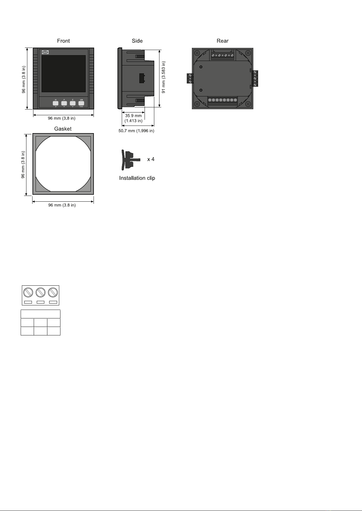
2.1.3 Dimensions
2.2 Communication (only MIB 8000C)
Suitable for SCADA systems, RS-485 serial output, and Modbus RTU protocol.
The communication port and protocol are RS-485 and Modbus RTU.
Communication
Comm Port
ABS
14 15 16
The terminals are A, B and S (14, 15, 16).
• A is differential data signal +
• B is differential data signal
• S is connected to a shield of twisted pair cables
The unit can handle up to 32 devices on the RS-485 bus. The maximum connection length is 1000 m. Conductors A and B should
be terminated with a 120 Ω (Ohm) terminating resistor at the end of the string. Use a baud rate of 9600 bps.
The MIB 8000C operates as server unit, and the client unit is normally a PC, PLC or a data collector of RTU. The communications
port of the client unit must have RS-485 port.
USB/RS-485 or RS-232/RS-485 converter can be used to convert signal for PC.
Use shielded twisted pair of cable AWG22 (0.6 mm2).
DESIGNER'S HANDBOOK 4189320063D EN Page 7 of 23

The shield of the RS-485 cable must be connected to the ground at one end only
2.3 Measurements
Measurement Description
Voltage Actual voltage of each phase-phase and phase-neutral.
Current Actual current of each phase and neutral current.
Active power (P) Active power of each phase.
Reactive power (Q) Reactive power of each phase.
Apparent power (S) Total apparent power.
Demand Demand of each phase current, active power and reactive
power.
Power factor (PF) Power factor of each phase and total power factor.
Min./max. : Min./max. of demand, voltage, current and active/reactive
power.
THD (up to 15th harmonics) Voltage/current THD of each phase.
Energy Import and export of energy, inductive and capacitive of reactive
energy.
Alarm Alarm can be related to any metering parameters.
Running hour Meters the duration of the operation
DESIGNER'S HANDBOOK 4189320063D EN Page 8 of 23

3. Measurements and functions
3.1 Measured and calculated values
Almost all the electric parameters in power systems can be measured by the MIB. Some of the parameters which are special will be
described in this part.
Reactive power (Q)
MIB adopts two definitions of reactive power:
1. Sinusoidal reactive power.
• The formula is as follows:
•
2. Nonsinusoidal reactive power.
• The formula is as follows:
•
Apparent power (S)
System total apparent power is measured and displayed.
Power factor (PF)
3-phase power factor and system total power factor are measured and displayed.
Frequency (F)
The frequency of L1 phase voltage input is measured as system frequency.
Energy (kWh)
Energy is time integral of power. The unit is kWh.
Import energy (imp)
"-"
Export energy (exp)
“+” is not shown in the display.
Reactive energy (kVArh)
Reactive energy is time integral of reactive power. The unit is kVArh.
Import energy (imp)
Capacitive energy.
Export energy (exp)
Inductive energy. Energy terms are based on the generator method.
Harmonic parameter : Total harmonic distortion
This factor is often used to express the power quality of the power system. The formula is as follows:
DESIGNER'S HANDBOOK 4189320063D EN Page 9 of 23

In the formula, U1 is RMS value of the voltage fundamental and Uh is RMS value of the voltage harmonic with order n.
Harmonic parameter : Each harmonic rate
The percentage of each harmonic divided by fundamental.
Demand
Demand of total power and reactive power of system, demand of 3-phase current. The demand statistics method in MIB is sliding
windows. The total sliding windows time can be chosen from 1 to 30 minutes. Each window slides once per minute.
Example
The sliding window time is supposed to be three minutes. If average power of the first minute is 12, 14 of the second
minute and third minute is 10.
Result of the total power demand the last three minutes is:
( 12 + 14 + 10 ) / 3 = 12 at the end of the third minute. If another minute passed, the average power of the minute is then 9,
then the total power demand of the last three minutes is ( 14 + 10 + 9 ) / 3 = 11 at the end of the forth minute.
Minutes
W, AAC, var, or VA
Example: 8 periods of 1 minute.
Sliding windows
Total of sliding windows
1 sliding window
Present MD Input
0 1 2 3 4 5 6 7 8 9 10 11 12 13 14 15 16 17 18 19 20
Unbalance factor
MIB can measure the unbalance factor of 3-phase voltage and current, using the method of sequence vector.
Max/Min: MIB can measure the max value of a system’s total power, reactive power and apparent power and the max/min of the 3-
phase voltage and current. The value of the measured data is stored in NV-RAM.
Alarm function
When the measured data value has reached the pre-set alarm limit and pre-set alarm time has expired, an alarm will be generated.
Digital output (only MIB 8000C with Extension module)
The digital output (DO) can be used to trigger a light or sound alarm indication. The following example describes how the over-limit
alarming works.
DESIGNER'S HANDBOOK 4189320063D EN Page 10 of 23
Table of contents
Other Deif Measuring Instrument manuals

Deif
Deif XDi Series User manual

Deif
Deif DLQA96 User manual

Deif
Deif Insight User manual

Deif
Deif ADL-111Q96/xxVDC Series Installation instructions

Deif
Deif BRW-2 User manual

Deif
Deif TRI-2 User manual

Deif
Deif XL User manual

Deif
Deif WSI User manual

Deif
Deif MIB 7000 User manual

Deif
Deif AGC 150 User manual