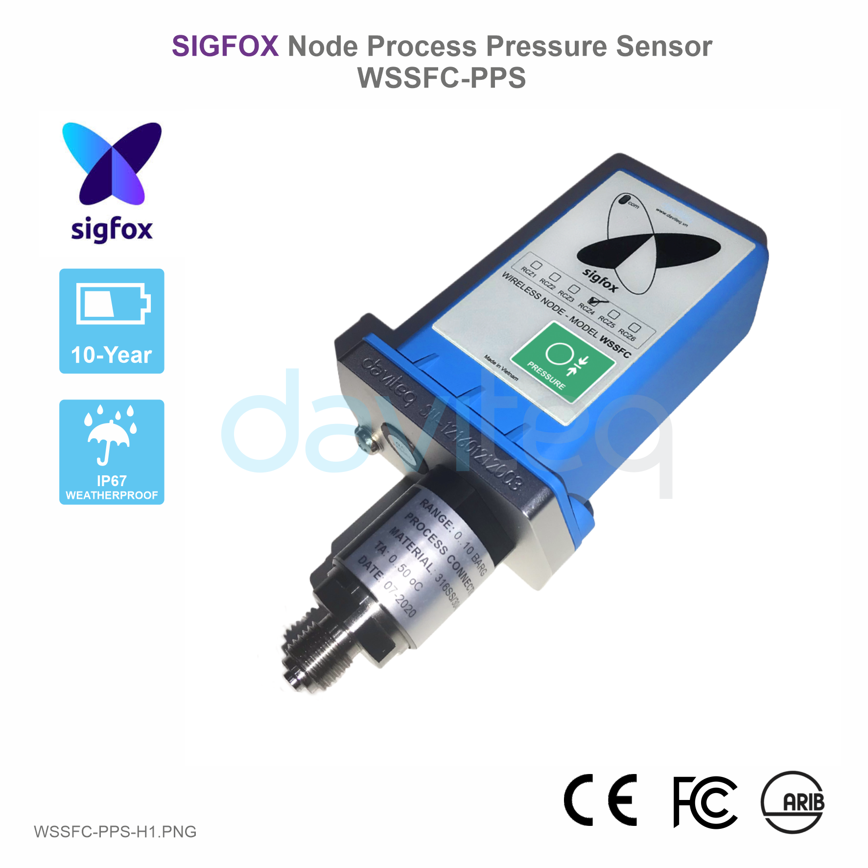
daviteq Sigfox WSSFC-PPS User manual

WSSFC-PPS -MN-EN-01
SEP-2020
SKU
WSSFC-PPS
HW Ver.
1.2
FW Ver.
1.2
Item Code
WSSFC-PPS-9-10
Sigfox Node Gage Process Pressure Sensor, Internal antenna, range 0-10 barg, accuracy 0.5%,
process connection G1/4-male, 304SS, Type AA battery 1.5VDC, IP67, RC2-RC3-RC4-RC5 zones
WSSFC-PPS-8-10
Sigfox Node Gage Process Pressure Sensor, Internal antenna, range 0-10 barg, accuracy 0.5%,
process connection G1/4-male, 304SS, Type AA battery 1.5VDC, IP67, RC1-RC6-RC7 zones
STEP 1: Select RC
1. Select RC zone
RC zones selection 1, 2, 4,... is RCZ1, RCZ2, RCZ4,... (refer to section
5)
STEP 2: Check ID and PAC
Use Modbus Configuration Cable to read the ID and PAC values
Refer to register address 8 and 10 (DEC)
USER GUIDE FOR SIGFOX NODE
PROCESS PRESSURE SENSOR
WSSFC-PPS
This document is applied for the following products
0. Configuration Check List

STEP 3: Configure the sensor's operating parameters
Configure parameters like cycle send data, alarm, a, b,...
Refer to the configuration section 5
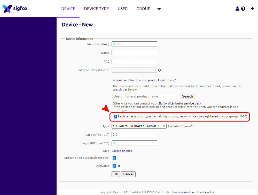
STEP 4: Add device to Backend Sigfox
refer to section 5.4 for details
STEP 5: Installation
refer to section 7 for details
Document Ver.
Release Date
Change log
1.0
SEP-2020
- First version for WSSFC-PPS
1.1
FEB-2022
- Update information
WSSFC-PPS is a Sigfox node integrated Process Pressure Sensor, and it has different kinds of measurements, such as
Gage/Absolute/Sealed Gage, range -1 .. + 700 bar, high accuracy, and stability. The sensor will transmit data in kilo-
meters distance to Sigfox basestation. WSSFC-PPS can support all regions of Sigfox network in over the World, RC1,
RC2, RC3, RC4, RC5, RC6, RC7.
SENSORS SPECIFICATION:
Sensor
Advanced PIEZO technology
Measurement range
Select from -1 .. + 700 bar Gage/Absolute/Sealed Gage
1. Change Log
2. Introduction
3. Specification

Over pressure protection
1.5 x Span
Accuracy & Stability
0.5% of span, < 0.3% span/year
Wetted parts
304SS/316SS
Measuring Fluids
Any fluid which is workable with materials 304SS/316SS
Working temperature
-10 .. + 80 oC
Process connection
Standard G1/4 or Others (consult factory)
Sigfox SPECIFICATION:
Sigfox zones
select RC2-RC3-RC4-RC5 or RC1-RC6-RC7
Antenna
Internal Antenna 2dbi
Battery
02 x AA Type 1.5VDC, working time up to 10 years (depends on
configuration)
RF Module complies to
CE, FCC, ARIB
Working temperature
-40oC..+60oC (using Energizer Lithium Ultimate AA battery)
Dimensions
H180xW50xD40
Net-weight
250 grams
Housing
Polycarbonate & POM plastic, IP67
4. Dimensions

After 1 minute 30 seconds later the device will send the first data packet and at the same time wait for the downlink
packet from the Base Station.
Then during the operation, there are 03 cases of sending data to base station:
1. When the sensor sampling time interval is reached, the Sigfox node will read the data from Input or sensor
and performing the calculation. After that it will check calculated value with alarm thresholds. If the calculated
was out off the threshold values (Lo or Hi), called alarm, and the number of times of alarm did not pass the limit
of number of alarms, then it will send data to Base station immediately;
2. When the sending time interval is reached, it will send data to Base station immediately, regardless of value;
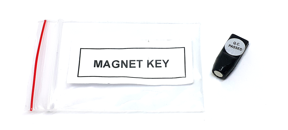
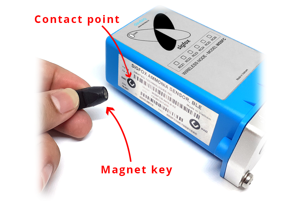
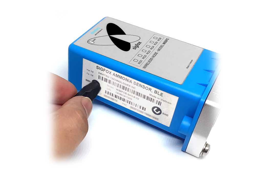
3. By using the magnet key, the Sigfox node can be triggered to send data to base station immediately. There
5. Operation Principle
Upon power on, the Sigfox node has 60 seconds to wait for off-line configuration (via cable with ModbusRTU
protocol)
NOTE:
Once sending the data to base station by this alarm event, the timer of sending time interval will be reset;

will be a beep sound from the buzzer meaning the data has been sent. (Buzzer will be updated in the latest
version)
EVENT
PRE-CONDITION
ACTION
LED STATUS
BUZZER STATUS
ACTIVITIES
POST-
CONDITION
FORCE_DATA
Any state
Move Magnet Key
to contact point of
REED SWITCH.
Buzzer beep 1
time, move
Magnet Key away.
Blink SKY BLUE
Beep 1 time
See FW specs
Back to previous
state
PARAMETERS_UPDATE
Any state
Move Magnet Key
to contact point of
REED SWITCH.
Buzzer beep 1
time, hold Magnet
Key 5s.
Buzzer beep 2
times.
Blink PURPLE
Beep 2 times
See FW specs
Back to previous
state
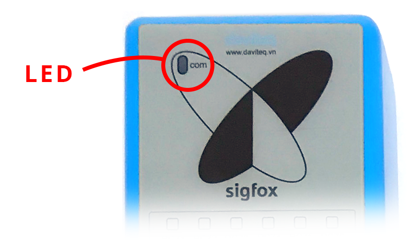
Whenever the data is sent to base station, the LED will lit with color codes as below:
RC1: RED colour
RC2: GREEN colour
RC4: BLUE colour
NOTE:
Once sending the data to base station by the magnet key, the timer of sending time interval will be reset;
The shortest time interval between the two manual triggers is 15s. if shorter than 15s, there will be no data
sending.
5.1 LED meaning

There are 3 configuration menus: tx_repeat, downlink_flag, radio configuration.
We use the button to enter the menus as follows:
Press and hold the button 2s -> When the Red LED is on, it means entering the tx_repeat configuration menu. Then
release to configure it.
Press to configure. After pressing if the Red LED flashes once, tx_repeat = 0 (send 1 time). After pressing if the Red
LED blinks twice, it is tx_repeat = 1 (send 3 times).
Press and hold the button 5s -> When the Green LED is on, it means entering the downlink_flag configuration
menu. Then release to configure it.
Press to configure. After pressing if the Green LED flashes once, it is downlink_flag = 0 (downlink is not allowed).
After pressing if the Red LED blinks twice, it is downlink_flag = 1 (downlink is allowed).
Press and hold the button 10s -> Blue LED is on, it means entering the Radio Configuration menu. Then release to
configure it.
Press to configure. After pressing if the Blue LED blinks once, it is Radio Configuration = 1. After pressing if the
Blue LED flashes twice, it is Radio Configuration = 2. After pressing if the Blue LED flashes 4 times, it is Radio
Configuration = 4.
There are 3 ways to exit the menu:
Press and hold for 3s, the LED turns off to exit the menu;
Wait 30 seconds, then exit the menu;
Take out the battery, it all starts over (outside the menu)).
The RF transmit power will be automatically set as the max value as allowed by the Zone.
Sigfox Radio Configuration (RC) defines the radio parameters in which the device shall operate: Sigfox operating
frequencies, output power, spectrum access mechanism, throughput, coexistence with other radio technologies, etc.
Each radio configuration includes 4 uplink classes: 0u, 1u, 2u, and 3u.
The Sigfox network globally works within the ranges from 862 to 928 MHz. But not all RCs require such a wide range of
operation.
5.2 Button Function
5.2.1 Menu configuration
5.2.1.1 tx_repeat
5.2.1.2 downlink_flag
5.2.1.3 radio configuration
5.2.2 Exit the menu:
5.3 RC technical details

RC1
RC2
RC4
Uplink center frequency (MHz)
868.130
902.200
920.800
Downlink center frequency (MHz)
869.525
905.200
922.300
Uplink data rate (bit/s)
100
600
600
Downlink data rate (bit/s)
600
600
600
Sigfox recommended EIRP (dBm)
16
24
24
Specifics
Duty cycle
1% *
Frequency
hopping **
Frequency
hopping **
* Duty cycle is 1% of the time per hour (36 seconds). For an 8 to 12 bytes payload, this means 6 messages per hour,
140 per day.
** Frequency hopping: The device broadcasts each message 3 times on 3 different frequencies. Maximum On time
400 ms per channel. No new emission before 20 s.
*** Listen Before Talk: Devices must verify that the Sigfox-operated 200 kHz channel is free of any signal stronger
than −80 dBm before transmitting.
Sigfox’s high limit EIRP recommendation is included in each column although regulations sometimes allow for more
radiated power than the Sigfox recommendation.
Sigfox’s recommendation is set to comply with the Sigfox technological approach of:
Low current consumption
Balanced link budget between uplink and downlink communication
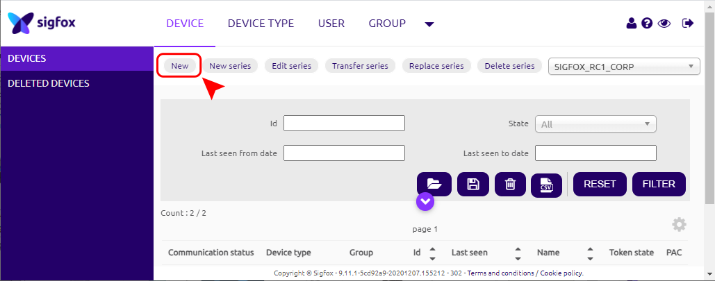
Step 1: Log in to the sigfox backend website
Step 2: Click on Device
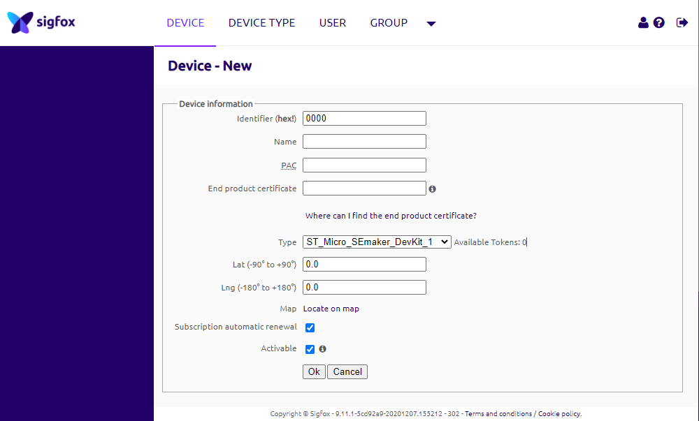
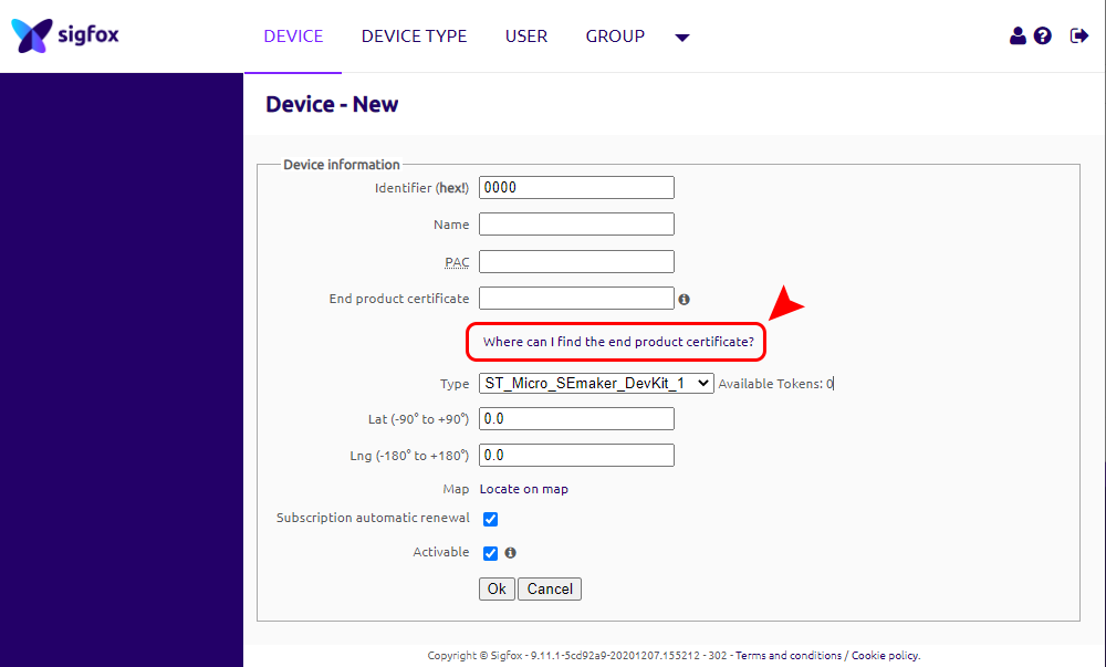
5.4 Add a device to the Backend Sigfox


When the sensor sampling time interval is reached, for example 2 minutes, the Sigfox node will wake up and switch ON
the power supply to supply the energy to external sensor to start the measurement. Depends on the type and
characteristic of external sensor, the sensor will take a certain time to finish the measurement.
Once reading the value, it can be scaled to any engineering value by the following formula:
Y = aX + b
Where:
X: the raw value from sensor
Y: the calculated value will be sent to Sigfox base station in the payload data.
a: constant (default value is 1)
b: constant (default value is 0)
So, if there is no user setting for a and b ==> Y = X
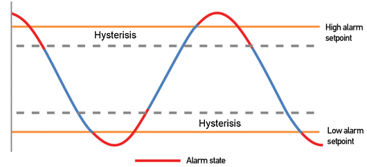
The Y value will be compared with Lo and Hi threshold. Please refer below the graph of alarm processing.
5.5 Process of measurement
This manual suits for next models
2
Table of contents
Other daviteq Measuring Instrument manuals