
CAB 4712 User manual

Assembly Instructions
4712
Made in Germany
Flag Applicator

2 2
Family Type
Flag Applicator 4712L-300
Edition: 03/2020 - Part No. 9009954
Copyright
This documentation as well as translation hereof are property of cab Produkttechnik GmbH & Co. KG.
The replication, conversion, duplication or divulgement of the whole manual or parts of it for other intentions than its original
intended purpose demand the previous written authorization by cab.
Editor
Regarding questions or comments please contact cab Produkttechnik GmbH & Co. KG.
Topicality
Due to the constant further development of our products discrepancies between documentation and products can occur.
Please check www.cab.de for the latest update.
Terms and conditions
Deliveries and performances are effected under the General conditions of sale of cab.
Assembly Instructions
for the following product
Germany
cab Produkttechnik GmbH & Co KG
Karlsruhe
Phone +49 721 6626 0
www.cab.de
USA
cab Technology, Inc.
Chelmsford, MA
Phone +1 978 250 8321
www.cab.de/us
Taiwan
cab Technology Co., Ltd.
Taipei
Phone +886 (02) 8227 3966
www.cab.de/tw
China
cab (Shanghai) Trading Co., Ltd.
Guangzhou
Phone +86 (020) 2831 7358
www.cab.de/cn
France
cab Technologies S.à.r.l.
Niedermodern
Phone +33 388 722501
www.cab.de/fr
Mexico
cab Technology, Inc.
Juárez
Phone +52 656 682 4301
www.cab.de/es
China
cab (Shanghai) Trading Co., Ltd.
Shanghai
Phone +86 (021) 6236 3161
www.cab.de/cn
South Africa
cab Technology (Pty) Ltd.
Randburg
Phone +27 11 886 3580
www.cab.de/za

3
Table of Contents
1 Introduction............................................................................................................................................4
1.1 Instructions...............................................................................................................................................4
1.2 Intended Use............................................................................................................................................4
1.3 Safety Instructions....................................................................................................................................4
1.4 Safety Markings .......................................................................................................................................5
1.5 Environment.............................................................................................................................................5
2 Product Description...............................................................................................................................6
2.1 Important Features...................................................................................................................................6
2.2 Technical Data..........................................................................................................................................6
2.3 Product Overview.....................................................................................................................................7
2.4 Contents of Delivery.................................................................................................................................8
3 Implementing..........................................................................................................................................9
3.1 Required Space ......................................................................................................................................9
3.2 Tools for the implementing.......................................................................................................................9
3.3 Mounting the Applicator..........................................................................................................................10
3.4 Mounting and Demounting the Cover .....................................................................................................11
3.5 Releasing the Transportation Lock..........................................................................................................11
3.6 CongurationonthePrinter ...................................................................................................................12
3.6.1 Method for Changing the Printer Setup............................................................................................12
3.6.2 CongurationParametersoftheApplicator......................................................................................13
3.7 Compressed Air Connection ..................................................................................................................14
3.8 Test motion sequence and sensors........................................................................................................14
3.9 Mounting the Suction Pads....................................................................................................................15
3.10 Mounting the Blow Tube.........................................................................................................................15
3.11 Preparing the Tamp Assembly for Adjustments......................................................................................16
3.12 Adjusting the Pad...................................................................................................................................17
3.12.1 Moving the Pad in Y-Direction ..........................................................................................................18
3.12.2 Moving the Pad in Z-Direction..........................................................................................................19
3.12.3 Moving the Pad in X-Direction..........................................................................................................20
3.13 Setting the Peel Position........................................................................................................................21
3.14 Activation of Peel-off Mode....................................................................................................................21
3.15 Adjustments to the Blow Tube (Supporting Air)......................................................................................22
3.16 Adjusting the Vacuum ............................................................................................................................23
3.17 Alignment of the Product to the Applicator.............................................................................................24
3.18 Setting the Application Height................................................................................................................25
4 Operation..............................................................................................................................................26
4.1 Test Mode without a Print Job................................................................................................................26
4.2 Test Mode with a Print Job.....................................................................................................................26
4.3 Standard Operation................................................................................................................................27
4.4 Cleaning.................................................................................................................................................27
5 Error Messages....................................................................................................................................28
5.1 Error Messages of the Printer................................................................................................................28
5.2 Error messages of the applicator...........................................................................................................28
6 Licenses................................................................................................................................................29
6.1 Declaration of Incorporation...................................................................................................................29
6.2 EU Declaration of Conformity.................................................................................................................30

4 4
1 Introduction
1.1 Instructions
Important information and instructions in this documentation are designated as follows:
Danger!
Draws attention to an exceptionally great, imminent danger to your health or life due to hazardous
voltages.
!
Danger!
Draws attention to a danger with high risk which, if not avoided, may result in death or serious injury.
!
Warning!
Draws attention to a danger with medium risk which, if not avoided, may result in death or serious injury.
!
Caution!
Draws attention to a danger with low risk which, if not avoided, may result in minor or moderate injury.
!
Attention!
Draws attention to potential risks of property damage or loss of quality.
i
Note!
Advice to make work routine easier or on important steps to be carried out.
Environment!
Gives you tips on protecting the environment.
Handling instruction
Reference to section, position, illustration number or document.
Option(accessories,peripheralequipment,specialttings).
Time Information in the display.
1.2 Intended Use
• The device is manufactured in accordance with the current technological status and the recognized safety rules.
However, danger to life and limb of the user or third parties and/or damage to the device and other tangible assets
can arise during use.
• The device may only be used for its intended purpose and if it is in perfect working order, and it must be used with
regard to safety and dangers as stated in the manual.
• The device is designed to use on a cab printer of the HERMES Q series. Any other use or use going beyond
this shall be regarded as improper use. The manufacturer/supplier shall not be liable for damage resulting from
unauthorized use; the user shall bear the risk alone.
• Usage for the intended purpose also includes complying with the manual.
i
Note!
The complete and current version of the documentation can be found in the Internet.
1.3 Safety Instructions
!
Attention!
Initiation, adjustments and changing of parts are to be performed by qualied service personnel only.
!
Warning!
This is a class A product. In a domestic environment this product may cause radio interference in which
case the user may be required to take adequate measures.

5
• Before mounting the delivered components disconnect the printer from the power supply and close the shutoff
valve of the applicator.
• Only connect the device to other devices which have a protective low voltage.
• Switch off all affected devices (computer, printer, accessories) before connecting or disconnecting.
• In operation, moving parts are easily accessible.
This applies especially for the zone, where the pad is moved between the starting and the labelling position.
During operation do not reach into that zone and keep long hair, loose clothes, and jewelry distant. Before any
manipulations in those areas, close the shutoff valve.
• The device may only be used in a dry environment, do not expose it to moisture (sprays of water, mists, etc.).
• Do not use the device in an explosive atmosphere.
• Do not use the device close to high-voltage power lines.
• Perform only those actions described in this manual.
Work going beyond this may only be performed by trained personnel or service technicians.
• Unauthorized interference with electronic modules or their software can cause malfunctions.
• Otherunauthorizedworkonormodicationstothedevicecanalsoendangeroperationalsafety.
• Alwayshaveserviceworkdoneinaqualiedworkshop,wherethepersonnelhavethetechnicalknowledgeand
tools required to do the necessary work.
• There are various warning stickers on the device. They draw your attention to dangers. Warning stickers must
therefore not be removed, as then you and other people cannot be aware of dangers and may be injured.
1.4 Safety Markings
1
3
2
1: Risk of injuries by moving parts!
2: The cylinder is under pressure
also if the printer is switched off.
Possibility of residual energy!
3: Danger of crushing hands and
ngersbythemovingpad!
!
Attention!
Never remove or cover safety markings!
Replace it in case of damage!
Fig. 1 Safety marking
1.5 Environment
Obsolete devices contain valuable recyclable materials that should be sent for recycling.
Send to suitable collection points, separately from residual waste.
The modular construction of the applicator enables it to be easily disassembled into its component parts.
Send the parts for recycling.
1 Introduction

6 6
2 Product Description
2.1 Important Features
• The supporting air and the vacuum as well as the speed of the cylinder are adjustable. That way the applicator
can be adapted to different label materials and sizes.
• For operation within a system the I/O interface of the printer can be used.
2.2 Technical Data
Ø
L
P
α
Ø
L
P
α
Diameter x π
Front side
Flag length L
Back side
Flag length L
Form pad
Technical data 4712 L 300
Label width Hermes+ 4 mm 60 - 100
Label height mm 10 - 50
Diameter mm 3 - 16
Product during labeling not in motion
Product labeling potmorf
wolebmorf
detatoryllacitrev 0- 180° clockwise; others on request
from the side
Product height
Product distance to lower edge of device mm.nim 70
at cylinder stroke 300 up to mm 260
Immersion depth tongs mm 55
up to mm 1.02)
Compressed air bar 4.5
Cycle time1) approx. labels/min 15
1) Calculated with print speed 100 mm/s
2) depending on the label quality
Fig. 2 Applicator parameters
Label transfer method Form-pad
Label width in mm for HERMES Q4 60 -100
Label height in mm 10 - 50
Diameter in mm 3 - 16
Compressed air pressure 0,45 MPa (4,5 bar)
Sound pressure level unter 74 dB(A)
Product during labeling xed ¢
in motion -
Labeling onto the
product from top ¢
from below ¢
vertically rotated 0 - 180° clockwise; others on request
from the side ¢
Product height xed ¢
variable -
Product distance to lower edge
at cylinder stroke min. mm 70
300 mm up to mm 260
Immersion depth tongs mm 55
Offset P up to mm 1,0 2)
Cycle time about frequency/min.1) 15
1) Determined at print speed 100 mm/s.
2) Depending on the label quality.
Table 1 Technical data
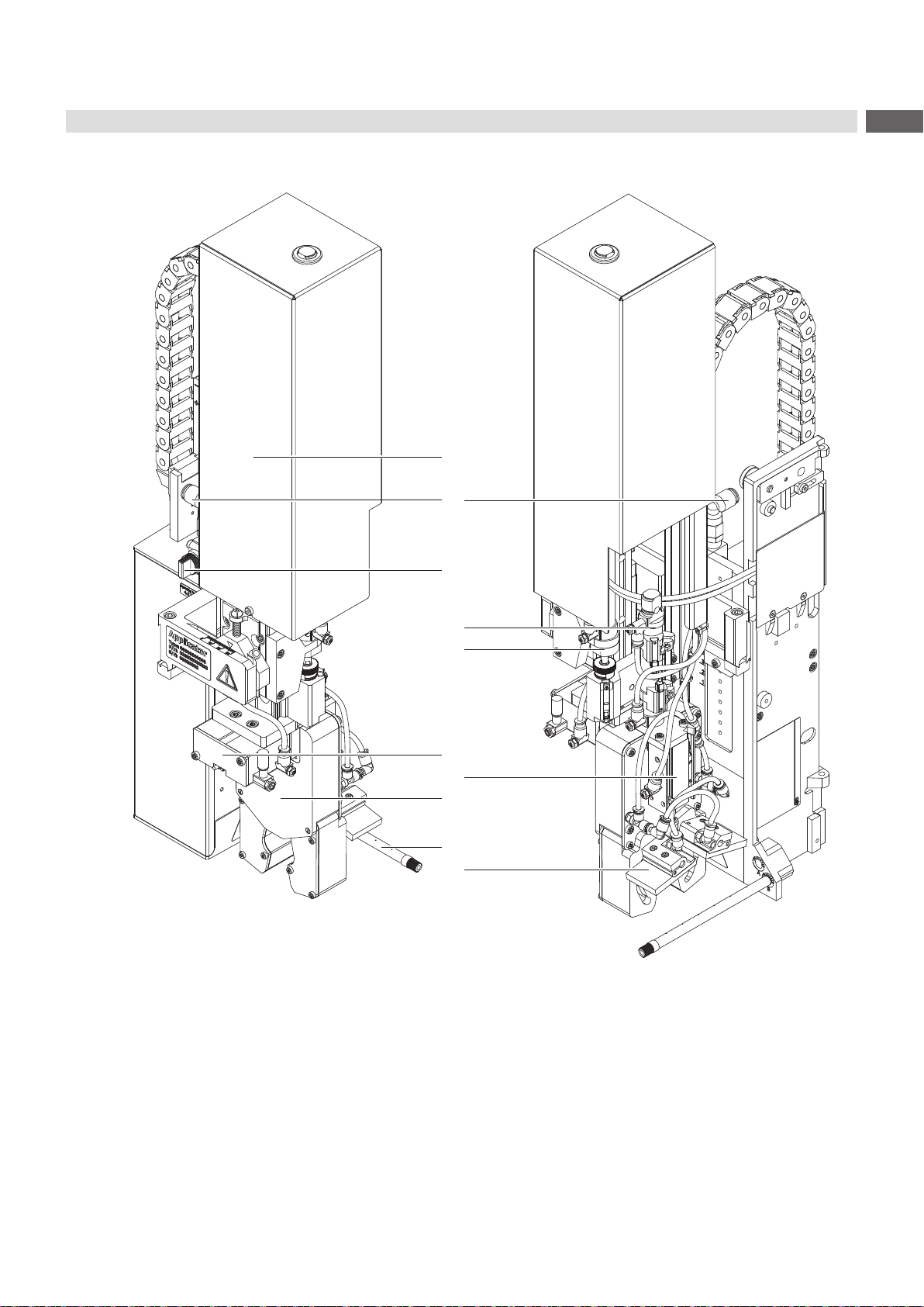

8 8
2.4 Contents of Delivery
3
1
2
• Applicator with mounted tamp assembly (1)
• Adjustment tool for the tamps (2)
• Blow tube for supporting air (3)
(depend of the used printer)
• Air pressure regulation unit (4)
• Documentation and test protocol
4
Fig. 4 Content of Delivery
i
Note!
Please keep the original packaging in case the applicator must be returned.
!
Attention!
The device and printing materials will be damaged by moisture and wetness.
Only set up the label printer with applicator in dry locations protected from moisture and splashes.
2 Product Description

9
3 Implementing
3.1 Required Space
min. 150 mm
min. 250 mm
print direction
Fig. 5 Disengaging or pivoting the applicator
3.2 Tools for the implementing
Screwdriver with parallel blade 2.5 To adjust the throttle valves and
product sensor
Hexagon key L-wrench 0.8 To adjust the sensors
(in contents of delivery)
2.5 For matched norm parts
(in contents of delivery)
4 Pad adjustments
Changing pad
Flat-round nose straight To mount/dismount tubes
angled
Open spanner SW 5.5 90° To change the pliers aperture
SW 8 To change the throttle valves
SW 13 Setting the spring power on the
adapter bolt
SW20 Changing the cylinder
Adjustment tool for the tamps cab part No.:
597285 Mounting the tamps

10 10
3.3 Mounting the Applicator
1
1
2
2
6
7
3
4
5
8 9 10
Fig. 6 Mounting applicator on printer
!
Attention!
Initiation, adjustments and changing of parts is only for qualied service personal only.
Service Manual
Mount the applicator
1. Hang the applicator with the female part of hinges (1) at the printer mounted hinges parts (2).
2. Connect SUB-D 15 male connector (6) to the female connector (7) of the printer.
3. To prevent the applicator from slipping out of the hinges loosen screw (4) and move the locking plate (3) under the
hinges and tighten screw (4).
4. Swing the applicator to the printer and tighten the thumbscrew (5).
5. Keep the external compressed air supply closed and close the shut-off valve (10) on the applicator see
illustration
6. Insert external compressed air supply (8) into the plug connector (9) on the shut-off valve (10).
7. Switch on compressed air and open shut-off valve (10) by turning 90 °.
For cleaning the applicator and printer it's sometime necessary to turn away or/and dismount the applicator.
Don't change the adjustments of setting screws, throttle valves or other.
Turn away/Dismount the applicator
8. To turn away the applicator loosen thumbscrew (5) and swing the applicator aside.
9. Disconnect SUB-D 15 male connector (6) to the female connector (7) of the printer.
10.Loosen screw (4) and move off the locking plate (3) from the hinges.
11. Lift the applicator upward.
3 Implementing
Other manuals for 4712
3
Table of contents
Other CAB Industrial Equipment manuals











