Bass EMD-RM Series Quick guide

EMD-RMTR.. User’s Manual
1
Installaton and Instructon
Manual
“Transmtter”
Electromagnetc Flowmeter
Type : EMD-RM...
Rv : 01

EMD-RMTR.. User’s Manual
2
Contents
1.General............................................... 3
2.Installaon.......................................... 3
3.Basic Circuit......................................... 9
4.Specificaons...................................... 10
5.Operaon and Setup........................... 11
6.Parameters and Setng....................... 12
7.Alarms.................................................. 22
8.Troubleshoong.................................. 22
EMD-RMTR.. User’s Manual
3
1. General
1.1. Intended Use
The electromagnetic flowmeters are designed exclusively to measure the flow and conducvity
of electrically conducve, liquid media.
1.2. Cerficaon
The device fulfils the statutory requirements of the following EC direcves:
• Low Voltage Direcve 2006/95/EC
• EMC Directive 2004/108/EC
• EN 61010
• EMC specification acc. to EN 61326/A1
The manufacturer cerfies successful tesng of the product by applying the CE marking.
2. Installaon
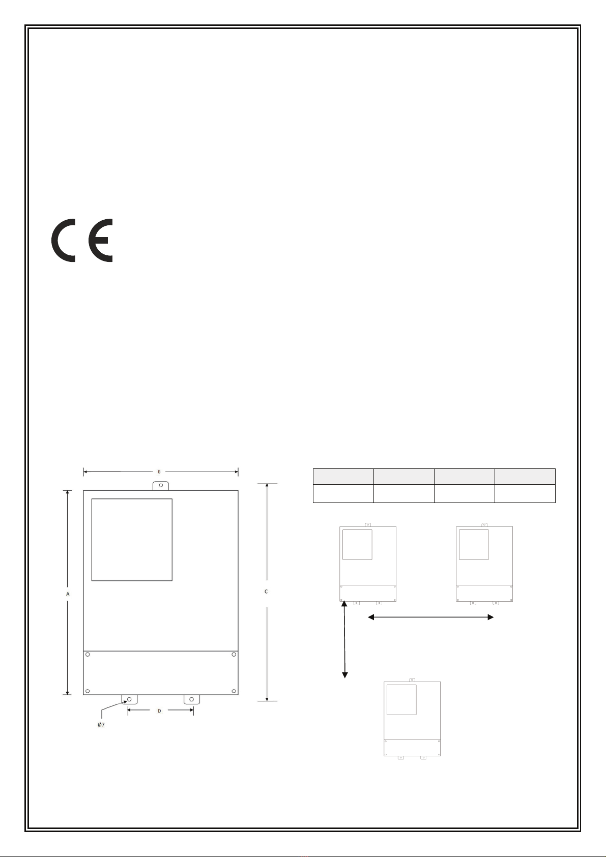
2.1 Dimension and mounng
mm
A B C D
214 164 234 70
300 mm
300 mm

EMD-RMTR.. User’s Manual
4
2.2 Terminal Wiring
Funcon Symbol Descripon
Pulse Output POUT Frequency (pulse) output
PCOM Pulse output Ground
Alarm Output ALMH Alarm Output for Upper Limit
ACOM Alarm Output Ground
Alarm Output ALML Alarm Output for Low Limit
ACOM Alarm Output Ground
RS485 (Optional) TRX+ Communicaon RS485+
TRX- Communicaon RS485-
Analog Current Output
VDIN 24V Pull Power Supply
IOUT Analog Current Output
ICOM Analog Current Output Ground
Power Supply
L or (-) 230VAC live or 24V DC (-)
N or (+) 230VAC notr or 24V DC (+)
Ground
Signal from Sensor
SIG1 Signal 1
SGND Signal Ground
SIG2 Signal 2
TCOM
EXT+ Excing Current+
EXT- Excing Current-
DS1 Shielded Excing1
MTSR
DS2 Shielded Excing2

EMD-RMTR.. User’s Manual
5
2.3 Sensor Wiring
2.4 Signal Outputs
2.4.1 Analog Output
Analog output wiring 4 to 20 mA (main connecon)
Blue : Signal 2
Red : Signal 1
Black : Signal GND
Red : EXT +
Black : EXT -

EMD-RMTR.. User’s Manual
6
There are two signal system:0 to 10mA and 4 to 20mA, it can be selected from parameter seng.
Simulaon signal output inner is 24V for 0 to 20mA, it can drive 750Ω resistance.
The percent flux of simulation signal output:
Iout : Measuring Value
Full Scale
For example ;
Measuring Value : 168 m3/h Full Scale : 200 m3/h Current Range : 20 – 4 mA : 16 mA I0 : 4 mA
(168/200)x16+4 : 17,44 mA
Current – Zero Point Calibraon
Enter “Parameter Seng”, and select “Analog Zero”. The standard of signal fountain geng to “0”. Adjust
parameter to ensure that the value of Amperometer is 4mA (±0.004mA).
Current – Full Scale Calibraon
Enter “Anlg Range”. Adjust parameter to ensure that the value of Amperometer is 20mA (±0.004mA)
2.4.2 Frequency,Pulse or Digital output
Frequency or pulse output wiring (main connecon)
x Current Range + I0
Counter,rate indicator
or PLC

EMD-RMTR.. User’s Manual
7
Pout
Pcom
P n
Com
User
equ pment
Vol t age nput
+
-
E
R
I ns de
The connection of digital voltage output
Table of digital output parameter: POUT
Parameter Test Condion Mini Typical Max Unit
Voltage IC=100 mA 3 24 36 V
Current Vol≤1.4V 0 300 350 mA
Frequency IC=100mA Vcc=24V 0 5000 7500 HZ
High voltage IC=100mA V
Low Voltage IC=100mA 0.9 1.0 1.4 V
User Side
Pout
Pcomm
24V-
24V+
24V-
24V+
DI
Com
24V-
24V+
1 K Ω
24V-24V+
Pull-up No Resstor;
EMD PLC (Elar, Setex, Sedomat)
Pout
Pcomm
24V-
24V+
24V-
24V+
DI
Com
24V-
24V+
24V-24V+
Pull-up wth Resstor;
EMD PLC (Elar, Setex, Sedomat)

EMD-RMTR.. User’s Manual
8
Frequency output
Digital output means frequency output and pulse output, and both of them use the same output point, so user
can choose only one type of them but not both.
Frequency output range is 0 to 5000Hz, and corresponding the percent of flux
f : Measuring Value
Full Scale
The up limit of frequency output can be adjusted. It can be chosen from 0 to 5000Hz, and also can be chosen
low frequency: such as 0 to 1000Hz or 0 to 5000Hz.
Frequency output mode can be used in control applicaon, because it responses the percent flux. Users can
choose pulse output when the equipment is applied to count.
Pulse Output
Pulse output mainly applies in count mode. A pulse output delegates a unit flux, such as 1L or 1 M3 etc. Pulse
output unit divide into 0.001L, 0.01L, 0.1L, 1L, 0.001 M3, 0.01 M3, 0.1 M3, 1 M3 .When the pulse unit is
selected, please noce the match of the flux range of flowmeter and pulse unit. For volume flux, count
formula as follows:
Q (l/sec) : 0,0007854 x ID2 x V
Q (m3/sec) : 0,0007854 x ID2 x V x 10-3
Where ; ID : Inside diameter (mm) V : Velocity ( m/sec)
The oversize flux and too small pulse unit will be made the pulse output over the up limit.
Generally, pulse output should be controlled below 3000 Pulses/Sec.
Otherwise, pulse output is different from frequency output. When pulse output cumulates a pulse unit, it
exports a pulse. Therefore, pulse output is not equality. Generally, measure pulse output should choose to
count instrument, but not frequent instrument.
Grounding
Contact area of copper Connector PE on Converter Cabinet for grounding should be larger than 1.6mm2.
Contact resistance should be less than 10Ω.
x frequency range

EMD-RMTR.. User’s Manual
9
3. Basic Circuit
32 bt
CPU
ROM
EEROM
LCD
Dsplay
Keyboard
A/D
exctng crcut
Swtchng
Power Supply
Current Output
Pulse Output
Status
Control
Communcaton
Interface
85~260V
45~63Hz
4-20mA or
0-10mA
1-5000Hz
Frequency or
Pulse Output
OC Gate Status
Output
RS485 .etc
preampl
fier
Working Principle: the converter supplies excing current to the coil of flowmeter’s sensor (Detector); the
main amplifier amplifies the electromove force from the sensor and converts it into standard signals of
current or frequency so that the signals can be used for displaying, controlling and processing. Structure of
converter circuit is shown in above figure

EMD-RMTR.. User’s Manual
10
4. Specificaons
Excing current can be selected for 125mA、187.5mA;
Velocity range: 0.1 to 15m/s,current speed resoluon: 0.5mm/s;
AC high-frequency switching power, range of voltage: 85VAC to 250VAC
DC 24V switching power, range of voltage: 20VDC to 36VDC
Network funcon: MODBUS、HART Communication (Oponal)
4.1 Especial Funcon
Recording time when power turn-off, to record power broken me of instrument system automatically and
recruit to count the missing flux
Recording function of hour gross, to record the flux gross by hour, fit for timed measure;
4.2 Normal Operang Condions
Ambient Temperature Ranges: –10~+60°C
Relative Humidity: 5%~90%;
Power Supply: 85...250V, 45~63Hz ( single-phase AC) or 20...36VDC
Dissipation Power: < 20W
4.3 Measure Precision
Range (m/s) Accuracy
0,1....0,3 ±0,25 % FS
0,3...1 ±0,5 % R
1...15 ±0,5 % R
Table of contents
Other Bass Measuring Instrument manuals


