ZWAE ONIII User manual

Installation and service manual
Zakład Wytwórczy Aparatów Elektrycznych Sp. z o.o.
ONIII
Outdoor disconnector 40kA
Manual No DTR.01.11.01.EN

Zakład Wytwórczy Aparatów Elektrycznych Sp. z o.o.
2
zwae.com.pl
WARNING
During the operation of electrical equipment, certain parts of
these devices are normally under dangerous voltage, and me-
chanical parts, also remotely controlled, can move quickly.
Failure to follow the warning instructions can result in serious
personal injury or material damage.
Only suitably qualied personnel can work on or near the de-
vice. This personnel must know exactly all safety rules and
rules for maintaining the device in accordance with these
instructions.
The problem-free and safe operation of this device requires
proper transport, proper storage, construction and assembly
as well as careful service and maintenance.

Zakład Wytwórczy Aparatów Elektrycznych Sp. z o.o.
3
Table of Contents
1. TRANSPORT ........................................ 4
1.1 Unpacking and inspection.............................. 4
1.2. Storage and transport................................. 4
2. DESCRIPTION ...................................... 6
2.1. Construction and principle of operation.................. 6
2.2. Climatic conditions................................... 6
2.3. Nameplate .......................................... 7
2.4. Basic technical parameters ............................ 7
3. INSTALLATION AND ADJUSTMENT .................... 8
3.1. Preparing contact surfaces ............................ 8
3.2. Poles adjustment .................................... 8
3.3. Disassembly of the transport lock ...................... 9
3.4. Operating mechanism assembly. . . . . . . . . . . . . . . . . . . . . . . . 10
3.5. Pole coupling and adjustment.......................... 10
3.6. Earthing switches coupling ............................ 13
3.7. Earthing switches operating regulation .................. 14
3.8. Grounding of the base frames.......................... 15
4. OPERATING MANUAL ................................ 15
4.1. Notes about connecting activities ...................... 15
5. INSPECTIONS AND MAINTENANCE .................... 16
5.1. Visual inspections.................................... 16
5.2.Periodical check-ups .................................. 16
5.3. Spare parts and recommended service materials ......... 17
6. UTILIZATION ........................................ 18
Zakład Wytwórczy Aparatów Elektrycznych Sp. z o.o.
4
1. TRANSPORT
1.1 Unpacking and inspection
Immediately after receiving the disconnector it should checked the delivery compliance with the shipping spec-
ication. Then should be checked whether the disconnector has not been mechanically damaged during trans-
port and the data on the nameplate match the order.
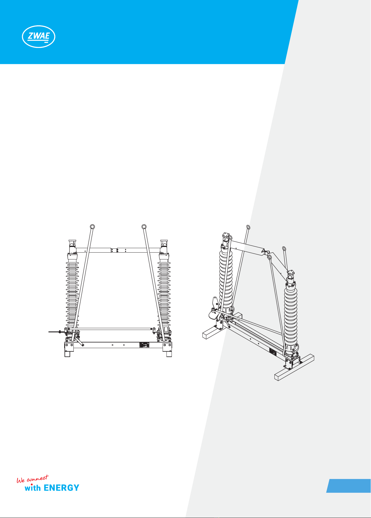
1.2. Storage and transport
Disconnector poles are transported in assembled condition. During the unloading and assembly process, the
disconnector poles should be lifted using transport belts, placed in the manner shown in the following graphic.
During transport, disconnector poles are placed on wooden beams, which should be removed immediately
before placing the pole on the supporting structure, unscrewing the four screws with a wrench size 13.

Zakład Wytwórczy Aparatów Elektrycznych Sp. z o.o.
5
During transport poles must be secured against tipping over and the central contact should be open. The dis-
connector can be transported by means of transport with open cargo area. On at, hard surfaces it is allowed
to move the disconnector’s poles with a pallet truck in the manner shown below, with particular care to prevent
the pole from tipping over.
Disconnector poles can be stored in an open space but poles should be put so that the base does not stand
directly on the ground.
psc

Zakład Wytwórczy Aparatów Elektrycznych Sp. z o.o.
6
2. DESCRIPTION
2.1. Construction and principle of operation
Outdoor disconnector type ONIII- ... is an insulating, two-column switch, with horizontal contacts movement.
It is designed to work in networks with voltage corresponding to the rated voltage, at frequencies up to 60 Hz
inclusive. The disconnector can be used as a single-pole switch with an individual operating mechanism or in
three-pole set with one common operating mechanism. Disconnector poles can be set in parallel or in serial
connection. Disconnector visual drawing in parallel conguration is shown below.
2.2. Climatic conditions
The disconnector is designed for outdoor operation, at ambient temperature from -50 to +40° C and relative
humidity up to 100%.
Current path
Base frame
Rotating base
Poles coupling mechanism
Left-sided earthing switch
Operating mechanism
Operating mechanism's supporting structure
Right-sided earthing switch
Earthing switches coupling mechanism

Zakład Wytwórczy Aparatów Elektrycznych Sp. z o.o.
7
2.3. Nameplate
2.4. Basic technical parameters
No. Parameter Value
1. Rated operating voltage 72,5 [kV] 123 [kV]
2. Rated current 1600 [A] 1600 [A]
3. Peak current 100 [kA] 100 [kA]
4. Short-circuit current, 1-sec. 40 [kA] 40 [kA]
5. Short-circuit current, 3-sec. 31,5 [kA] 31,5 [kA]
6.
Test voltage (50 Hz) for insulation:
- to earth and between phases,
- between contacts of one pole.
140 [kV]
160 [kV]
230 [kV]
265 [kV]
7.
Surge test voltage for insulation:
- to earth and between phases,
- between contacts of one pole.
325 [kV]
375 [kV]
550 [kV]
630 [kV]
8. Radio interference voltage <1000 [µV] <1000 [µV]
9. Rated mechanical operating life: 2000 cycles 2000 cycles
10.
Dedicated operating mechanism:
- motor,
- manual.
NSO80
NR-5
NSO80
NR-5

Zakład Wytwórczy Aparatów Elektrycznych Sp. z o.o.
8
3. INSTALLATION AND ADJUSTMENT
The delivered disconnector is completely regulated and ready to work. Assembly is reduced to:
a) installation poles on a supporting structure,
b) attaching supporting construction for the operating mechanisms,
c) installation of operating mechanisms,
d) poles coupling and regulation,
e) earthing switches coupling,
f) earthing switches regulation,
g) grounding the base frame and operating mechanisms.
3.1. Preparing contact surfaces
Contacts resistance depends primarily on the quality and cleanliness of the contact surface. These surfaces
should be very precisely prepared. The method of preparing aluminum and silver contacts surfaces is de-
scribed below:
• aluminum – aluminum connection
Remove the oxide layer from the contact surface with a wire brush. After this treatment, the surface should be
matt gray, devoid of shiny areas. Clearly remove shavings and aluminum dust from the surface, for example by
lubricating with acid-free grease and then removing it. After this treatment, the surface should be greased with
acid-free grease to protect it from oxidation of aluminum. The prepared surface should not be exposed to the
atmosphere longer than the time needed to prepare the cooperating surface.
• copper – silver connection
The copper surfaces should be cleaned of oxides with a brass wire brush and then proceed as for the aluminum
surface. Silver surfaces do not need to be cleaned with a brush, but they can be cleaned with a mild abrasive,
for example steel wool. After cleaning, cover the surface with a thin layer of acid-free grease.
3.2. Poles adjustment
The disconnector poles should be placed on the supporting structure, which has mounting holes in accordance
with the drawing below.

Zakład Wytwórczy Aparatów Elektrycznych Sp. z o.o.
9
3.3. Disassembly of the transport lock
Remove the transport blockade from the poles attached to the supporting structure.
To remove the blockage, unscrew the M10 screw in the disconnector base frame and the M12 screw in the drive
lever has to be unscrewed. After removing the blockade, the M12 screw must be crewed back in the same place.

Zakład Wytwórczy Aparatów Elektrycznych Sp. z o.o.
10
3.4. Operating mechanism assembly
The operating mechanism should be mounted on the supporting structure, under driving crank located in dis-
connector base. After the operating mechanism is assembled, the coupling shaft must be attached to connect
the operating mechanism to the crank. The assembly method is shown in the gure below.
Tightening torque: M12 - 80 Nm, M16 - 100 Nm.
3.5. Pole coupling and adjustment
After setting the poles on the supporting structure, check the end positions of the current paths and, if neces-
sary, correct the position of the bumpers and the lengths of the shafts of the disconnector kinematic system.
After checking the correctness of operation of the poles the coupling rods can be assembled.
Operating mechanism's
supporting structure
Operating mechanism
Crank gear
Coupling shaft
Current path position adjustment screws
Current path rotation angle limit bumper
Other manuals for ONIII
2
Table of contents
Other ZWAE Industrial Equipment manuals


