
Vutlan VT960i User manual

VT335i / Remote Monitoring Unit
Documentation page: https://vutlan.atlassian.net/l/c/gTr18F3Q
Product page: https://vutlan.com/remote-monitoring-units/164-vt335i-monitoring-unit.html
Function and purpose
The unit is used for environmental monitoring (e.g. temperature, humidity, voltage, leakage, smoke, airflow). It is also used
as an I/O controller (e.g. door control, fans, generator, control panels, UPS, circuit breakers, alarms). Can use up to 700
different elements - notifications, triggers, timers, logic schemes, sensors, dry contacts. Has built-in Web interface with virtual
sensors, logic schemes, different types of notification, and control panels. Has a slot for an LTE modem for an ethernet
connection reservation.
Physical Description
Front panel:
VT335i is a new model and it replaces VT335S. New features include:
two times more powerful processor.
ability to handle more elements (+200)
slightly smaller dimensions
slot modem
power reservation
USB camera higher max. resolution

Back panel:
1. " .. " - x8 RJ12 6P4C analog sensor inputs with auto-sensing. Read instructions at "Analog sensors: A1 A8 Analog sensors
", " ".connection Sensor configuration
2. " " - digital connector RJ12 6P4C for the connection of CAN sensors/extensions/devices on a CAN bus. Modules can be CAN
chained together. Read instructions at " ", " ".CAN devises connection Setting up CAN
" " - green LED indicates CAN bus status.LED: CAN
The LED blinks slowly - nothing is connected
The LED blinks fast - configuration is in process
The LED glows constantly - connected to CAN devices
3. " " - Ethernet 10/100 Base-T port, provides an Ethernet connection. Read more in this section "LAN port LAN, GSM, LTE,
".RADIUS, DNS, SSL, VPN
" " - orange LED for Ethernet port. It shows network traffic.Orange LED
" " - green LED for Ethernet port. It shows network traffic. Flashes green when the system starts up. Shows Green LED
the connection state (constant green light - the connection is established, blinking green - the connection attempt).
4. " " - MicroSD card slot with an ejector. The card is needed for data storage or the "system restore". Read SD card
instructions at " ", " ".Saving system logs to SD card Restore of the appliance (for VT960 series)
5. " " - accuracy +/- 1 °C.TEMPERATURE SENSOR
6a. " " - green LED indicates appliance system status,LED: ACT
- operating mode of the device: switches at a frequency of 2 times per second;
- successful completion of the software update process: switches at a frequency of 4 times per second;
6b. " " - The button can be programmed from the interface for alarm indication.LED: ALARM
6c. " " - red LED indicates error and traffic.LED: ERR
the operating mode of the device: If everything is normal, the LED is extinguished, if not - there's a constant glow;
software update mode: switches at a rate of 2 times per second;
6d. " " - green LED indicates CAN bus status.LED: CAN
7. " " - micro USB-port 2.0 is needed for USB camera recording, USB Flash for system logs, and the system restore. Read USB
instructions at " ", " ", " "Connecting USB camera USB camera settings. How to save a video Saving system logs on USB flash drive
, " ".USB upgrade or restore of default settings
8. " " Dip switch
Normal mode: The switch is switched to the left . The switch should be always in this position.
Recovery mode: The switch is switched to the right . Use this option only in case you need to recover manufacturing
settings.
9. - 12V 0.25A (for each output) terminals outputs (electronic relay). Pitch 3.81mm, 3P. Read "OUTPUTS 12V 0.25A"
instructions at " ".Connecting 12V devices to 12V outputs
" " - status indicators for two 12V 0.25A output on the front panel.LEDs: E1, E2
The LED is ON (orange) - the output is ON (the initial state can be configured).
The LED is OFF (orange) - the output is OFF ((the initial state can be configured).
10. " " - Chassis grounding, M4 thread. Enhances the immunity of the equipment against conducted and Chassis grounding
radiated RF disturbances. Please contact a professional electrician before connecting it.
11. " " - A hole for mounting GNSS antenna. Antennas are purchased separately from VT335i and separately from VT740. GNSS
Read more at , and .GPS location GPS Service API
12a. " " - the button restarts the appliance. Hold the button for 2 seconds and then let go, the system will restart.Restart
12b. " " - reset smoke sensors. Read more at .Reset settings Operation of smoke detectors in dusty conditions
12c. " " - reset settings to default factory settings.Factory reset
13. " " - "VT790 / LTE slot modem" can be installed in this slot. Modem slot
Read instructions This modem is ordered separately.
at "VT790 / LTE slot modem", "LAN, GSM, LTE, RADIUS, DNS, SSL, VPN".
14. " " - Digital inputs (Type IN). Pitch 3.5mm, 6P. Read instructions at " ", "DRY CONTACT INPUTS 1...4 Connecting dry contacts
".Dry contacts settings
15. " " - 12V DC 2A alternative power input. Pitch 3.81mm, 2P.DC 12V BACKUP POWER
16. " "- 12V DC 2A main power input.DC 12V POWER
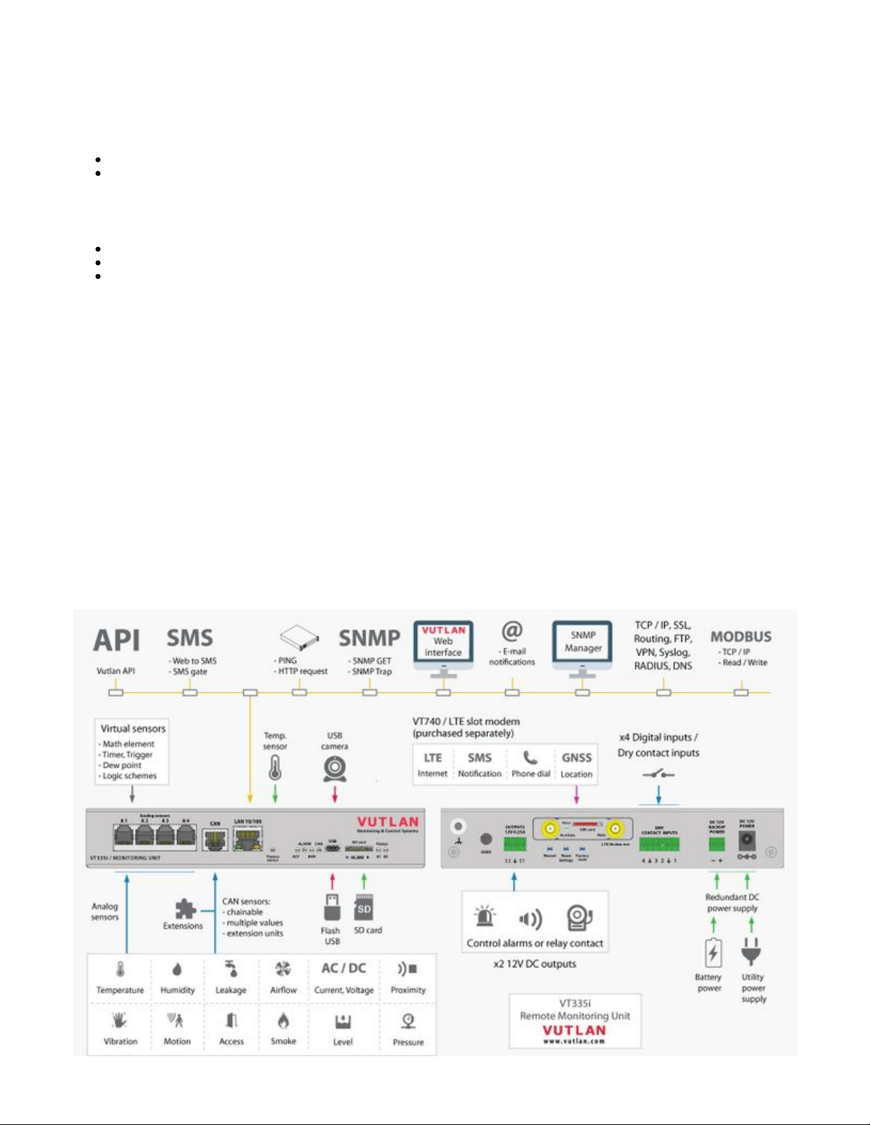
Connection overview diagram


1.
2.
3.
4.
Usage
Can be installed in VT960i v3, VT960ii v3, VT855i v2.6, VT855ii v2.6, VT825i v2.6, VT825ii v2.6, VT335i monitoring systems.
Description
4G LTE slot modem for Vutlan monitoring units. Allows to receive and send SMS messages. Provides Ethernet over 4G LTE.
Power-cycling is an embedded function.
Panel
" " - Connector, used when the modem is installed inside of the appliance to connect LTE auxiliary antenna. The Auxiliary
additional antenna helps to strengthen the signal level. (Auxiliary LTE antenna and antenna output are ordered
separately from the modem).
" " - displays modems status. Blinking = working.Status
"SIM card" - SIM card slot with an injector.
" " - Connector, used when the modem is installed inside of the appliance to connect GSM or LTE main Main antenna
antenna. (The main antenna is supplied together with the modem).
Installation
You can install the modem while the system is turned On. You may wait up to 3 minutes until the Telecom operator
information is renewed.
Step 1 1.1 Use the to cut off wire cutter tool
the labeled “metal panel LTE Modem
”.slot
You can dispose of the metal panel
after.
VT740 has a miniature RF connector on the board for connecting GNSS antenna. GNSS antenna is not sold together
with VT740.

Step 2 Plug the as VT740 slot modem
shown on the picture into the
opening. The board should slide into
the guide rails (marked as “1”) and
plug into the jack (marked as “2”).
Step 3 3.1 Screw the main LTE antenna into
“ ” jack.Main” antenna
3.2 If you want to strengthen the
signal, you can screw in the second
auxiliary antenna into “ ” Auxiliary
jack.

1.
Step 4 Plug in the . The SIM card SIM card
slot has an .injector
Step 5 You are ready to go! Turn on the
system.
You can install the modem while the
system is turned On. You may wait
up to 3 minutes until the Telecom
operator information is renewed.
Configuring the modem
Please read the following section for the configuration instructions:
Online documentation page link: Setting up a modem
The direct page link for users with paper documentation:
https://vutlan.atlassian.net/wiki/spaces/DEN/pages/1016347/Setting+up+a+modem
Accessories
“ ” for mounting on DIN rail. VT124 is ordered separately. The package includes a holder and VT124 / DIN rail holder
screws.

2. “ ” for mounting onto the wall. The package includes 2 brackets and screws.VT123 / Wall mounting brackets
3. “ ” for mounting onto a 19” 1U rackmount.VT122i / 19” holder
Inventory
Make sure that the contents of the delivery meet the following configuration. Report a missing or damaged component to your
supplier. If damage occurred during transportation, contact the appropriate delivery service.
Package content Description

1 Monitoring unit VT335i.
2 12V adapter.
3 RJ-45 3m patch cable
4OTG Micro USB cable adater
5 Terminal plug 6 pins, 3.5 mm - 1 pc
6 Terminal plug 3 pins, 3.81 mm - 1 pc

7
Terminal plug 2 pins, 3.81 mm -1pc
8 Self-adhesive rubber foot - 4 pcs
9 Configuration manual
10 Warranty card
Other manuals for VT960i
1
This manual suits for next models
5
Table of contents
Other Vutlan Measuring Instrument manuals


