
Vaillant 065 008 Guide
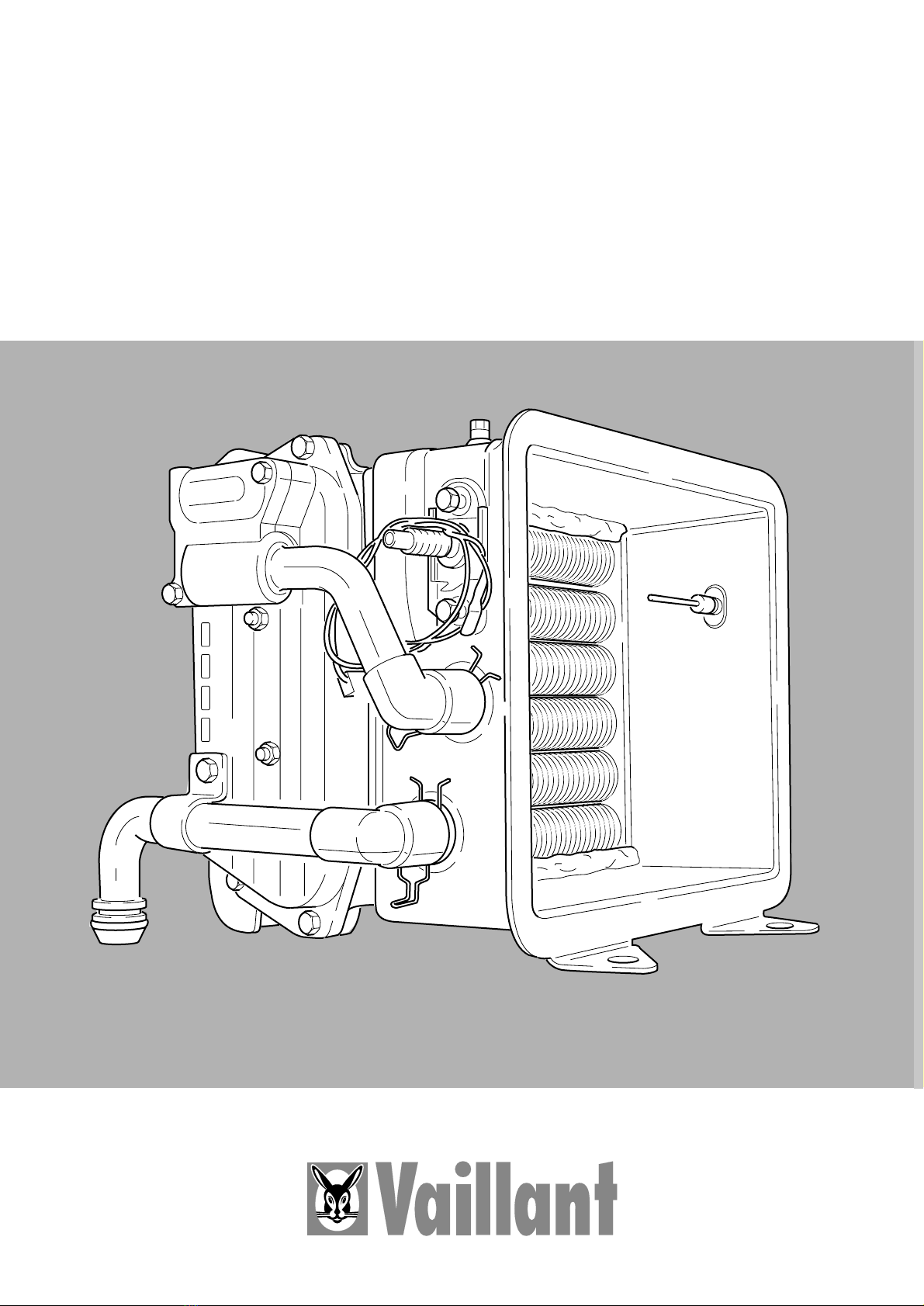
Integral condensing heat exchanger
Primaire warmtewisselaar
Article number: 065 008 (28 kW), 065 007 (23 kW)
Artikelnummer 06-4991 (28 kW), 06-4993 (23 kW)
INSTRUCTIONS FOR INSTALLATION
MONTAGEVOORSCHRIFT

2
Fig. 1.1
Legend to fig. 1.1
1 heat exchanger
2 sealing profile
3 flow pipe
4 bow
5 return pipe
6 clamp
7 oval head screw
8 hexagon nut
9 rectangular sealing ring
10 spring
11 ignition plug
12 NTC lead extension wire
GW 878/1

3
Please read these instructions for
installation thoroughly before
working on the appliance. These
instructions contain important notes on
the replacement of the spare part.
Please refer also to the instructions for
installation and servicing, supplied
with the boiler.
We do not accept any responsibility
for damage caused by the non-
observance of these instructions for
installation.
Contents Page
1 Equipment 3
2 Defined application 3
3 Precautions 3
4 Preliminary measures 4
5 Pre-assembly of the
new integral condensing
heat exchanger 5
6 Removal of the old
heat exchanger 6
7 Installation of the new
integral heat exchanger 13
8 Commissioning 15
1 Equipment
The spare parts kits for the heat
exchanger, art. no. 065 008 (28 kW)
and 065 007 (23 kW) contain the
following components:
1 heat exchanger
2 sealing profile (2)
3 flow pipe
4 bow
5 return pipe
6 clamp
7 oval head screw (2)
8 hexagon nut (4)
9 rectangular sealing ring (2)
10 spring
11 ignition plug
12 NTC extension lead
(pre-asssembled)
2 Defined application
The existing heat exchanger may only
be replaced by the Vaillant integral
condensing heat exchanger in the
following appliances:
•Art.-Nr. 065 007 (23 kW) for:
VUW 236, VU 186
•Art.-Nr. 065 008 (28 kW) for:
VUW 286, VU 226
Only original Vaillant spare parts must
be used.
The valid spare part catalogue indica-
tes the necessary spare parts. Informa-
tion on this subject can be obtained
from the Vaillant sales department.
3 Precautions
The replacement of the heat exchan-
ger, must only be carried out by a
competent installer who is also respon-
sible for the correct installation and
recommissioning.
In the UK ”CORGI”registered instal-
lers undertake the work to a safe and
satisfactory standard.
Furthermore, the rules and regulations
mentioned in the instructions for instal-
lation and servicing must be observed.

4
Fig. 4.1
4 Preliminary measures
•Completely remove the front panels
according to the instructions for
installation and servicing supplied
with the boiler.
•Remove the combustion chamber
front cover.
•Turn off appliance by switching off
main switch.
•Pull off air orifice (1); see fig. 4.1.
High flow temperatures may cause
burns and scalds.
Check flow temperature and cool
appliance, if necessary.
Cooling the appliance
•Turn on appliance by switching on
main switch.
•Ensure heat demand,
For VUW, open a hot water tap.
For VU, turn on all external controls.
The appliance remains in the start
mode. There is, however, no igniti-
on and no gas supply. The pump
and the fan are in operation and
cool the appliance. The ignition
cycle is stopped by the control after
3 minutes. (Fault signalling F 30).
During this period the boiler should
be sufficiently cooled.
•Check appliance temperature,
repeat above procedure if required.
•Turn off appliance by switching off
main switch.
•Isolate the boiler from the electrical
supply by disconnecting the plug at
the socket outlet (if there is an isola-
ting switch only, then remove the
fuse from the switch).
GW 879/0
5
Fig. 5.1
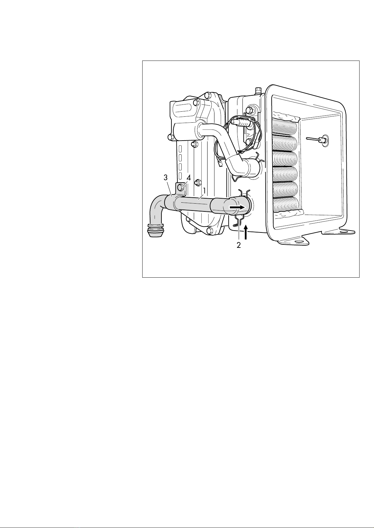
5 Pre-assembly of the
new integral conden-
sing heat exchanger
•Remove transport plugs from the
flow and return connections of the
new integral condensing heat
exchanger.
Keep transport plugs as they are
necessary for the return of the old
heat exchanger.
•Insert return pipe (1) in the return
connection of the heat exchanger.
Lock with spring (2).
Fix return pipe with clamp (3) and
screw (4) to the heat exchanger.
•The flow pipe is mounted later on
when the heat exchanger has been
installed.
GW 880/0

6 Removal of the old
primary heat
exchanger
Preliminary measures
•Release control box and tilt for-
wards.
•Check automatic air vent adjacent
to pump, open it if closed.
•Turn off central heating service
values (flow and return).
•Attach a length of rubber tube to
draining points and drain the water
from the boiler into a suitable con-
tainer by undoing the drain points
one turn (drain points located abo-
ve flow and return service valves).
Removal
Pull off the following plug-in connec-
tions –start at the fan and proceed
anti-clockwise:
•control (1) and supply connection
(2) at the fan
•Plug (3) of the supervision electrode
•AMP-plug (4) at the NTC-sensor of
the heat exchanger on the left
•Two AMP-plugs (5, 6) at the NTC-
sensors of the flow pipe
•Ignition plug (7) and earth cable (8)
at the ignition electrode
•Unscrew ignition plug (7) from HT
lead by turning it to the left; release
plastic cable tie of cable (11).
•Screw new ignition plug included in
the replacement set to the HT lead.
The small opening of the black insula-
tion socket of the ignition plug causes
a slight mechanical resistance when
the plug is screwed down. Screw into
HT lead to the limit stop.
•Release NTC earth (9) at the flow
pipe. Keep screw (10) for later use!
6
NOTE Abb. 6.1
GW 881/0

7
Fig. 6.2
Fig. 6.3
•Undo union on the flow pipe (1) at
the T-piece (see fig. 6.2). Remove
sealing washer and brass restrictor.
The restrictor should be discarded
as it is no longer required.
The lower front panel (2) of the
appliance can be used to collect
any water.
Up to 0.5 l water will be released.
(fig. 6.3)
•Remove spring (1) which secures
the flow pipe (2) at the heat
exchanger.
•Detach flow pipe.
GW 882/0
GW 883/0

(fig. 6.4)
•Remove spring (1) of the return
pipe (2) at the heat exchanger.
Do not remove the spring (3) neces-
sary for securing the connecting
pipe to the combustion chamber!
If the connecting pipe is released from
the combustion chamber, it will be
necessary to remove the complete
appliance from the wall.
8
Fig. 6.4
Fig. 6.5
NOTE
!
•Remove return pipe (1) and plug it
into a different socket for better
draining as shown in Fig. 6.5.
The lower front panel (2) of the
appliance can be used as collec-
ting pan.
Up to 0,5 l water will be released.
GW 884/0
GW 898/0

9
Fig. 6.6
Fig. 6.7
•Pull lock (1, fig. 6.6) forwards by
using a screw driver or similar. The
flue gas duct is released from the
flue collector box/condensation
sump.
(fig. 6.7)
•Pull forward captive spring (1) at
the condensation trap.
•Press condensation trap down-
wards.
Note: Some appliances are equipped
with a condensation water pipe with
bayonet fixing. This can be disconnec-
ted by pulling the handle forwards.
GW 886/0
GW 899/0

•Lift leaf springs (1 and 2, fig. 6.9)
at the burner and pull forwards to
remove –see fig. 6.8 –.
•Keep leaf springs for further use.
Only release spring as shown in
fig. 6.8.
10
Fig. 6.9
Fig. 6.8
NOTE
GW 888/0
GW 900/0
This manual suits for next models
3
Table of contents
Languages:
Other Vaillant Industrial Equipment manuals











