Toa C-CV854R-3 CU User manual

Thank you for purchasing TOA Vandal Resistant Day/Night IR Camera.
Please carefully follow the instructions in this manual to ensure long, trouble-free use of your equipment.
VANDAL RESISTANT
DAY/NIGHT IR CAMERA C-CV854R-3 CU
INSTRUCTION MANUAL

2
TABLE OF CONTENTS
1. SAFETY PRECAUTIONS .................................................................................. 3
2. HANDLING PRECAUTIONS ............................................................................ 5
3. GENERAL DESCRIPTION ............................................................................... 5
4. FEATURES ............................................................................................................ 6
5. NOMENCLATURE ............................................................................................... 7
6. INSTALLATION
6.1. Detaching a Dome Cover ................................................................................... 8
6.2. Installing a Camera ............................................................................................ 8
6.2.1. Unexposed wiring .................................................................................... 8
6.2.2. Open wiring from the camera's side ....................................................... 10
7. CONNECTION .................................................................................................... 12
8. ADJUSTMENT .................................................................................................... 13
9. ABOUT THE MODE SETTING SWITCH
9.1. Focus Adjustment Switch ................................................................................. 16
9.2. Backlight Compensation Switch ....................................................................... 16
9.3. Flickerless Switch ............................................................................................ 16
9.4. ATW/AWB Selection Switch ............................................................................ 17
9.5. High-Sensitivity Switch ..................................................................................... 17
9.6. Average/Peak Selection Switch ....................................................................... 17
10. TROUBLE SHOOTING .................................................................................... 18
11. SPECIFICATIONS ............................................................................................. 19
Accessories .............................................................................................................. 20

3
1. SAFETY PRECAUTIONS
• Before installation or use, be sure to carefully read all the instructions in this section for correct and safe
operation.
• Make sure to observe the instructions in this manual as the conventions of safety symbols and messages
regarded as very important precautions are included.
• We also recommend you keep this instruction manual handy for future reference.
Safety Symbol and Message Conventions
Safety symbols and messages described below are used in this manual to prevent bodily injury and property
damage which could result from mishandling. Before operating your product, read this manual first and
understand the safety symbols and messages so you are thoroughly aware of the potential safety hazards.
Do not leave the unit upside-down where it could be exposed to the
rain or elements. Water in the unit may cause shorts that could result
in fire or electrical shock.
WARNING
Indicates a potentially hazardous situation which, if mishandled, could
result in death or serious personal injury.
WARNING
• Do not touch the camera with wet hands. Installing or setting the camera with wet hands may result in
electrical shock.
• Use the unit only with the voltage specified on the unit. Using a voltage higher than that which is specified
may result in fire or electric shock.
• Use screws that are appropriate for the ceiling's or wall's structure and composition. Failure to do so may
cause the unit to fall, resulting in material damage and possible personal injury.
• Ensure that all screws and fixing mechanism are securely tightened. If they are not tightened or firmly
secured after installation, the unit could fall down, possibly resulting in personal injury.
• Install the unit only in a location that can structurally support the weight of the unit and the mounting bracket.
Doing otherwise may result in the unit falling down and causing personal injury and/or property damage.
• Avoid installing the unit in locations exposed to sea breeze or corrosive gas. The unit or its mounts may be
subject to corrosion, that might cause it to fall or result in other accidents.
• If any of the following irregularities occurs, immediately turn off the power supply, and inform the shop from
where the unit was purchased. Further using the unit may result in fire or electric shock.
· If you detect smoke or a strange smell coming from the unit.
· If water or any metallic object gets into the unit.
· If the unit falls, or the unit case breaks.
· If the power supply cord is damaged (exposure of the core, disconnection, etc.)
· If it is malfunctioning (no image appears.)
• To prevent a fire or electric shock, never open nor remove the unit case as there are high voltage
components inside the unit. Refer all servicing to qualified service personnel.
• Do not mount the unit in locations exposed to constant vibration. The mounting screws and/or bolts may be
loosened by excessive vibration, potentially causing the unit to fall, which could result in personal injury.
• To prevent lightning strikes, install the unit at least five meters away from a lightning rod, and yet within the
protective range (angle of 45°) of the lightning conductor. Lightning strikes may cause a fire, electric shock
or personal injury.
• Do not insert nor drop metallic objects or flammable materials in the ventilation slots of the unit's cover, as
this may result in fire or electric shock.

4
Indicates a potentially hazardous situation which, if mishandled, could
result in moderate or minor personal injury, and/or property damage.
CAUTION
• Leave the installation of the unit to your TOA dealer because the installation requires expert experience and
skills. The unit may fall off if incorrectly installed, resulting in possible personal injury.
• Do not stand or sit on, nor hang down from the unit as this may cause it to fall down or drop, resulting in
personal injury and/or property damage.
• Have the unit checked periodically by the shop from where it was purchased. Failure to do so may result in
corrosion or damage to the unit that could cause it to fall, possibly causing personal injury.
• Switch off the power for safety purposes when cleaning or leaving the unit unused for 10 days or more.
Doing otherwise may cause a fire or electric shock.
Note
This equipment has been tested and found to comply with the limits for a Class B digital device,
pursuant to Part 15 of the FCC Rules. These limits are designed to provide reasonable protection
against harmful interference in a residential installation. This equipment generates, uses and can
radiate radio frequency energy and, if not installed and used in accordance with the instructions, may
cause harmful interference to radio communications. However, there is no guarantee that interference
will not occur in a particular installation. If this equipment does cause harmful interference to radio or
television reception, which can be determined by turning the equipment off and on, the user is
encouraged to try to correct the interference by one or more of the following measures:
•Reorient or relocate the receiving antenna.
•Increase the separation between the equipment and receiver.
•Connect the equipment into an outlet on a circuit different from that to which the receiver is connected.
•Consult the dealer or an experienced radio/ TV technician for help.
Modifications
Any modifications made to this device that are not approved by TOA Corporation may void the authority
granted to the user by the FCC to operate this equipment.
CU version complies with Part 15 of the FCC Rules.

5
2. HANDLING PRECAUTIONS
• Do not direct the camera lens to the sun, strong lighting, or reflected light. If strong light enters the lens, this
may cause the CCD's internal color filter to deteriorate, leading to image discoloration.
• Do not give the camera a great shock or vibration to avoid camera damage.
• It is recommended that the camera be always used in locations where the ambient temperature ranges from
-
10°C to +50°C (14°F to 122°F) and humidity levels of less than 90% to ensure that no condensation is
formed.
• To clean, wipe with a dry soft cloth. Never use benzene, thinner or chemically processed towel as the
camera's plastic or other parts may be deformed or discolored.
• When dust has settled on the unit's lens, lightly clean using a commercial camera blower or cleaning paper.
• Installing the camera cables in close proximity to fluorescent lamps or other electrical appliances can
downgrade the picture quality. In such cases, change the wiring.
• If there is a strong electric or magnetic field near the camera, such as television transmission antennas,
motors or transformers, this may distort or roll the monitor picture. In such cases, run the entire wiring route
through metal conduit tubing.
• Do not install the unit in locations where solvents or chemicals are used as the unit's dome cover may be
deformed or discolored.
• When operating on 12 V DC, use the external power supply rated at 12 V DC and over 1.0 A.
• Since the Day/Night camera features sealed construction, condensation can build up inside the camera,
causing the inside of the dome cover to fog. Ensure that the camera is installed under low humidity
conditions.
• Avoid installing the Day/Night IR camera in locations exposed to cold air or close to an air-conditioner outlet
vent, as the dome cover may become fogged.
3. GENERAL DESCRIPTION
The C-CV854R-3 is Vandal Resistant Day/Night IR Camera equipped with a Day/Night function. It functions
as a color camera (day mode) in bright locations and as a high-sensitivity black & white camera (night mode)
in dark locations. Since the camera's built-in infrared LED illuminator lights in night mode, video surveillance is
possible even in no light conditions, allowing the camera to be used for around-the-clock surveillance. Noise
reduction function enables low noise, clear images to be viewed even under poor lighting conditions. Its dust-
proof and waterproof (IP66) construction permits it to be mounted to an outdoor wall or ceiling without using a
special device. Since the camera unit is constructed of die-cast aluminum alloy and its dome section is made
of polycarbonate, it ensures high resistance to strong impacts. It features a 3-axis (horizontal, vertical and
rotation) adjustment mechanism and a 3x varifocal lens which facilitate adjustment of camera orientation and
view angle at the time of installation.
The power is supplied from 24 V AC or 12 V DC external power source. The use of an optional heater unit
allows the C-CV854R-3 to be used at ambient temperatures as low as
-
30°C (
-
22°F.)

6
4. FEATURES
•Built-in 3x Varifocal Lens
Owing to a built-in auto iris 3x varifocal lens (f=3 - 9 mm), the angle of view can be adjusted.
•Adjustment Switch
The infrared camera is equipped with an adjustment switch that facilitates the manual adjustment of lens
focus. Turning on this switch forcibly makes the depth of field shallow, allowing finer focus adjustment.
•Day & Night Mode
By mechanically inserting and extracting the infrared block filter, the camera can function as a color camera
(day mode) in bright locations and as a high-sensitivity black & white camera (night mode) in dark locations.
The camera switches from day mode to night mode at a brightness level of approximately 2 lx, while night
mode switches to day mode at approximately 10 lx. There is a standby time of approximately 5 seconds
before the mode switches in order to prevent malfunctions resulting form momentary changes in brightness
(such as headlights).
•Internal Infrared LED Illuminator
The internal infrared LED illuminator lights in night mode and allows subjects to be viewed even in
environments where no lighting equipment is installed. The infrared LED's irradiation distance is as follows;
Indoor irradiation distance: Approx. 18 m (59.06 ft.)
Outdoor irradiation distance: Approx. 15 m (49.21 ft.) (High-sensitivity switch OFF)
•Noise Reduction
Since the camera is equipped with noise reduction circuitry, it can pick up images with less noise even in
low-light scenes. Also, the camera's reduced noise permits video recording to be more efficiently performed
using a digital video recorder.
•Backlight Compensation
This function reduces the darkening of subject images due to backlighting.
•White Balance
Selection can be made of either automatic tracking white balance (ATW), which automatically adjusts the
camera's white balance as the subject's color temperature changes, or automatic white balance (AWB),
which keeps the white balance at the adjusted level.
•High-Sensitivity Function (Slow-Speed Shutter)
The camera's automatic gain control (AGC) operates when images become dark. However, if the image
remains dark, the camera's high-sensitivity function works to obtain a brighter image. This is done by
extending the light exposure time during which the electrical charge is stored in the image pickup device.
(After-image blurs may be produced by quickly moving subjects.)

7
[Side view with a dome cover attached]
[Bottom view with a dome cover attached]
[Side view with a dome cover detached]
[Bottom view with a dome cover detached]
1
2
3
5
4
6
7
8
9
13
12
11
15
14
10
(1) Camera power input cable (Red, Black)
(24 V AC or 12 V DC)
(2) Heater power input cable (White, White)
(24 V AC)
(3) Video output terminal (cable with BNC)
(4) Safety wire fixing hole (M4)
(5) Zoom ring fixing screw
(6) Zoom ring
(7) Focus ring fixing screw
(8) Focus ring
(9) Lens cover
(10) Mode setting switch
(11) Iris control
(12) Monitor output terminal (RCA pin jack)
(13) Infrared LED
(14) Shield ring
(15) Varifocal lens
5. NOMENCLATURE

8
6. INSTALLATION
Notes
• Do not remove the protective sheet attached to the dome cover until installation work is completed. Damage
to the dome cover could result if the protective sheet is removed during installation.
• A safety wire for connecting between the unit and ceiling is not supplied. Hook a safety wire for the unit itself
to the safety wire-fixing hole (M4, useful thread depth = 6 mm (0.24")) as needed.
• Wrap self-adhesive insulation tape around coaxial cable connections and the power supply lead.
6.1. Detaching a Dome Cover
1. Detach the dome cover from the case.
Remove three screws fixing the dome cover with a supplied L-type wrench.
Notes
• The dome cover is connected to the case by a safety wire.
• You may find that an O-ring placed into the groove of the dome cover is about to come off when detaching
the dome cover. In such cases, replace the O-ring into the groove securely.
LOCK
LOCK
L-type wrench
Dome cover
Case
41 (1.61)
83.5 (3.29)
46 (1.81)
Camera unit
mounting hole
Cable entry hole
ø20 (0.79)
Camera center
Unit: mm (inch)
6.2. Installing a Camera
6.2.1. Unexposed wiring
1. Make a cable entry hole as shown at right in the
ceiling or wall.
Note
When mounting the camera to a wall, make sure the
cable entry hole is positioned below the camera
center.

9
2. Connect a coaxial cable to the camera's BNC output terminal.
When operating on 24 V AC or 12 V DC, connect the power cable wires to the camera power input cable
(Red, Black).
3. Fix the camera unit to the ceiling or wall using the four mounting screws.
Attach the supplied base gasket to the camera unit, then install the camera unit to the ceiling or wall. Since
no mounting screws are supplied with the camera, prepare them separately depending on the situation.
(Use screws that are over 4 mm (0.16") in nominal diameter and longer than 25 mm (1").)
Base gasket
Note
The cable trench and four camera mounting holes must be protected with silicone sealant material to prevent
rainwater from leaking into the enclosure. Do not waterproof other holes.
Sealant material (4)
Sealant material
[Cable trench] [Camera mounting holes]

10
Cord bush
Pipe receptacle thread cover
Fixing screw
Cord bush
6.2.2. Open wiring from the camera's side
Note: The pipe receptacle thread on the camera's side is compatible with 3/4-inch threaded conduit.
1. Loosen the fixing screw with a standard driver, then detach the camera side-attached pipe receptacle
thread cover.
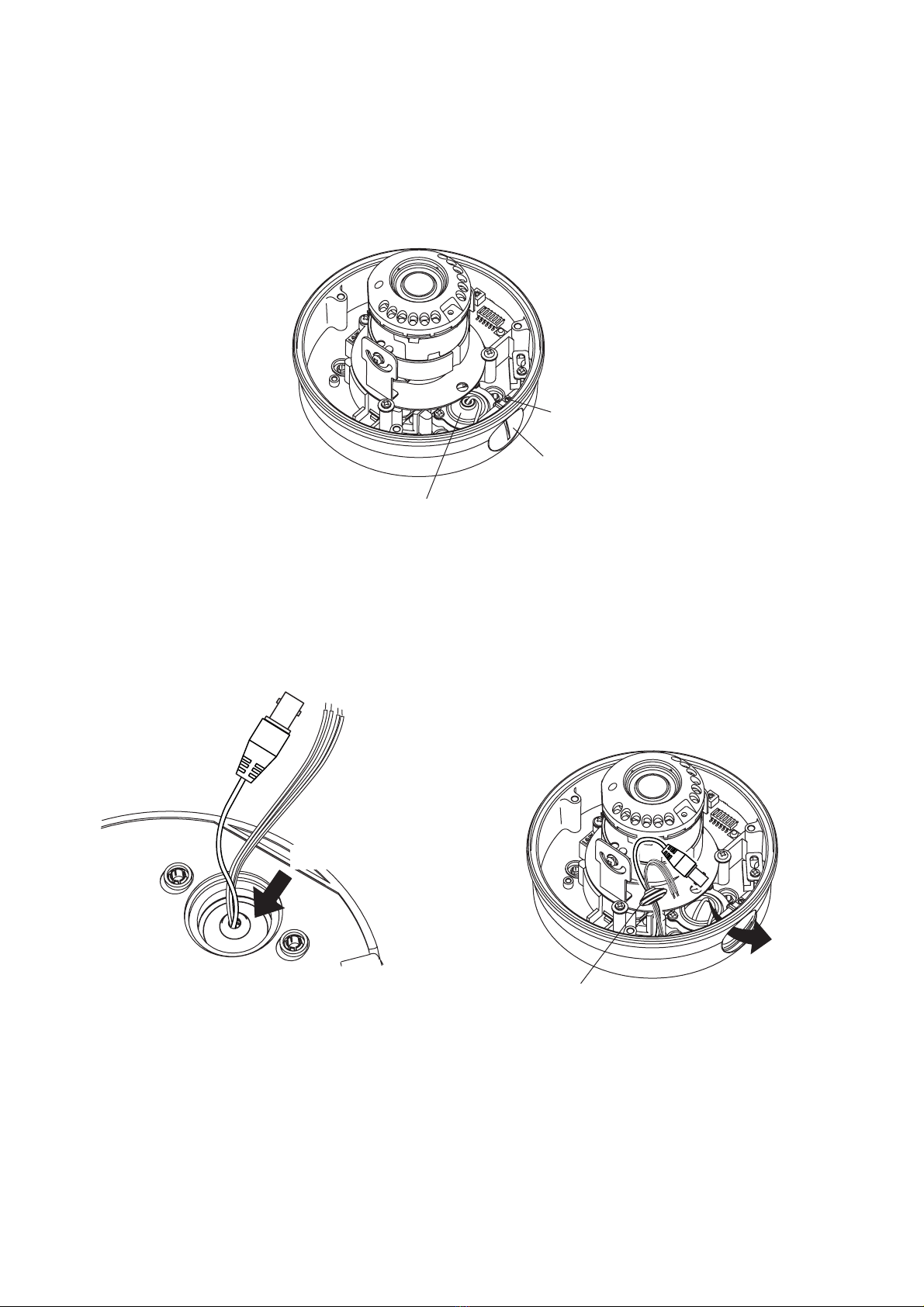
2. Push in the cord bush attached to the camera unit from the back to pull out from the case. Run the cable
and lead it out from the camera pipe receptacle thread hole.
Push the cord bush.
Table of contents
Other Toa IP Camera manuals