SWR SolidFlow 2.0 User manual

EN
Operating Instructions
SolidFlow 2.0
Solid volume measurement

Operating Instructions
2
TABLE OF CONTENTS Page
1. System overview .......................................................................3
2. Function .............................................................................. 5
3. Safety ................................................................................ 6
3.1 Normal use ....................................................................... 6
3.2 Identification of hazards ............................................................ 6
3.3 Operational safety .................................................................. 6
3.4 Technical statement ................................................................ 6
4. Mounting and installation .............................................................. 7
4.1 Typical components of the measurement point . . . . . . . . . . . . . . . . . . . . . . . . . . . . . . . . . . . . . . . . . 7
4.2 Required equipment ................................................................ 7
4.3 Sensor installation ................................................................. 7
4.4 Mounting the transmitter .......................................................... 10
4.5 Use in hazardous areas ............................................................ 12
5. Electrical connection ..................................................................13
5.1 DIN rail terminal layout ............................................................ 13
5.2 Field housing terminal layout ....................................................... 14
5.3 C1-box terminal layout ............................................................. 15
5.4 C3-box terminal layout ............................................................. 15
6. Operator interface .................................................................... 16
6.1 Differences between the DIN rail and field housing transmitter . . . . . . . . . . . . . . . . . . . . . . . . . . 16
6.2 Display .......................................................................... 17
6.3 PC interface ..................................................................... 18
6.4 One or more sensor system ......................................................... 20
6.5 Menu structure ................................................................... 21
7. Start-up procedure ................................................................... 29
7.1 Basic start-up .................................................................... 29
7.2 Adjusting the measurement values .................................................. 29
8. Maintenance ......................................................................... 30
9. Warranty ............................................................................ 30
10. Troubleshooting ...................................................................... 30
11. Technical data ....................................................................... 31

Operating Instructions
3
1. System overview
A measuring point consists of the following components:
•Transmitter (in the DIN rail housing or field housing)
•Sensor mount for welding to the pipeline
•Sensor (union nut, spacer rings, sealing ring for adjusting to the wall thickness)
•Installation instructions
•C1- or C3-box
Sensor C1-Box Transmitter
max. 300 m
2 m
1 (+ 24 V)
2 (GND)
3 (A)
4 (B)
S (Earth)
C1-Box
Sensor
C1-Box
Sensor
16 (+ 24 V)
15 (GND)
14 (A)
13 (B)
Sensor C1-Box Transmitter
max. 300 m
2 m
Fig. 1: Overview with C1-box and field housing transmitter
Fig. 2: Overview with C1-box and DIN rail transmitter

Operating Instructions
4
TransmitterC3-Box
Sensor
Sensor
Sensor
2 m max. 300 m
1 (+ 24 V)
2 (GND)
3 (A)
4 (B)
Shield
The system can be equipped with up to three sensors. Different C-boxes (C1, C3) are used accordingly.
Fig. 3: Overview with C3-box and field housing transmitter
Fig. 4: Overview with C3-box and DIN rail transmitter
Transmitter
C3-Box
2 m max. 300 m
16 (+ 24 V)
15 (GND)
14 (A)
13 (B)

Operating Instructions
5
Fig. 5: Integration and reflection of microwaves
2. Function
•The SolidFlow 2.0 is a measuring system which has been specially developed for measuring the quantity
of solids conveyed in pipelines.
•The sensor works with the latest microwave technology. It is only used in metallic pipelines. The special
integration of microwave technology together with the metallic pipeline creates a homogeneous
measurement field.
•The microwave radiation in the pipeline is reflected by the solid particles and received by the sensor.
The frequency and amplitude of the received signals are analysed.
•The frequency-selected evaluation system ensures that only moving particles are measured and
deposits are suppressed.
•SolidFlow 2.0 features active stratification compensation which increases measurement accuracy.

Operating Instructions
6
3. Safety
The SolidFlow 2.0 measuring system has a state of the art, reliable design. It was tested and found to be in a
perfectly safe condition when leaving the factory. Nevertheless, the system components may present dangers to
personnel and items if they are not operated correctly.
Therefore, the operating manual must be read in full and the safety instructions followed to the letter.
If the device is not used correctly for its intended purpose the manufacturer's liability and warranty will be void.
3.1 Normal use
•The measuring system may only be installed in metallic pipes to measure the medium passing through
them.
It is not suitable for any other use or measuring system modifications.
•Only genuine spare parts and accessories from SWR engineering may be used.
3.2 Identification of hazards
•Possible dangers when using the measuring system are highlighted in the operating instructions with
the following symbols:
Warning!
•This symbol is used in the operating manual to denote actions which, if not performed correctly may
result in death or injury.
Attention!
•This symbol is used in the operating manual to denote actions which
may result in danger to property.
3.3 Operational safety
•The measuring system may only be installed by trained, authorised personnel.
•During all maintenance, cleaning and inspection work on the pipelines or SolidFlow 2.0 components,
make sure that the system is in an unpressurised state.
•Switch off the power supply before performing any maintenance work, cleaning work or inspections on
the pipelines or the SolidFlow 2.0 components. See the instructions in the section entitled Maintenance
and care.
•The sensor must be taken out of the pipeline before any welding work is performed.
•The components and electrical connections must be inspected for damage at regular intervals. If any
signs of damage are found, they must be rectified before the devices are used again.
3.4 Technical statement
•The manufacturer reserves the right to adjust technical data concerning technical developments without
notice. SWR engineering will be delighted to provide information about the current version of the
operating manual, and any amendments made.

Operating Instructions
7
4. Mounting and installation
4.1 Typical components of the measurement point:
•Transmitter in the DIN rail housing or field housing
•Sensor mount for welding to the pipeline
•Sensor (union nut, spacer rings, sealing ring for adjusting to the wall thickness)
•Installation instructions
•C1- or C3-box
4.2 Required equipment
•Ø 20 mm-twist drill bit
•32 mm open-ended spanner for union nut
•Locking ring pliers (Ø 20 mm) to adjust the sensor to the wall thickness
4.3 Sensor installation
Proceed as follows to install the sensor:
•Decide on the installation position on the pipe. It should be installed from the top on horizontal or
angled pipelines.
•Note: Depending on the application, up to 3 sensors can be used on pipeline diameters larger than
200 mm, whereby the sensors must be mounted 120 mm apart and offset in relation to each other at an
angle of 120°.
•The distances apply to vertical and horizontal installations.
•Ensure that the measurement point is at an adequate distance from valves, manifolds, blowers and
bucket wheel feeders and other measurement ports such as those used for pressure and temperature
sensors, etc. (See Fig. 6)
Fig. 6: Minimum distances of the measurement point from pipe geometries and fittings
•On free-fall applications (for example, after screw conveyors or bucket wheel feeders), a drop height of
at least 300 mm is ideal.

Operating Instructions
8
•Weld the sensor mount to the pipe.
•Drill through the pipe through the sensor plug (Ø 20 mm). Ensure that the borehole is not angled so that
the sensor can be installed precisely at a later stage.
Attention!
•After drilling, it is essential to check whether the drill bit has caused any burrs on the borehole edges.
Any burrs on the pipe must be removed using a suitable tool. If the burrs are not removed they may
affect the sensor's calibration.
•If the sensor is not installed immediately insert a plug until it is installed (see also Fig. 7). The plug must
be inserted together with the seal, two sealing rings and the locking ring, and secured using the union
nut.
Use a 32 mm open-ended spanner to tighten the union nut.
Fig. 7: Install the sensor mount
and the plug
Spacer ring 1 mm
Round seal 19 x 2
Sensor mount
Union nut
Locking ring
Plug
q
q
q
q
q
q
q
•Remove the sealing plug to insert the sensor.
•The sensor is supplied pre-assembled for the specified wall thickness or, if no wall thickness was
specified, to a wall thickness of 4 mm. Check again that it is correctly adjusted before installation
(see table). If necessary, the wall thickness must be remeasured using a depth gauge. The weld-on
socket is 93 mm long. It is important that the sensor does not project into the pipe. The sensor may be
up to 1 mm inside the pipe wall without this causing a measurement error.
Wall thickness (mm) Position on the sensor neck Number of spacer rings
3.0
4.0
5.5
6.5
8.0
9.0
10.5
11.5
13.0
14.0
1
1
2
2
3
3
4
4
5
5
2
1
2
1
2
1
2
1
2
1

Operating Instructions
9
•Now insert the sensor into the sensor guide as shown in Figure 8a.
Fig. 8a: Install the
sensor mount
and the sensor
Sensor mount
Round seal 19 x 2
Spacer ring(s) 1 mm each
Locking ring 20 x 1.2
Padding ring 1 mm
Union nut
Sensor
q
q
q
q
q
q
q
1
2
• and align it longitudinally to the pipe axis as shown on the polarisation sticker (Fig. 8b).
Then seal the measurement point with the union nut.
Fig. 8b: Sensor alignment
▼
Flow direction
• Make sure you install a drip loop with the cable anywhere it may get wet to prevent
water flow from reaching the sensor.
Drip Loops
Operating Instructions
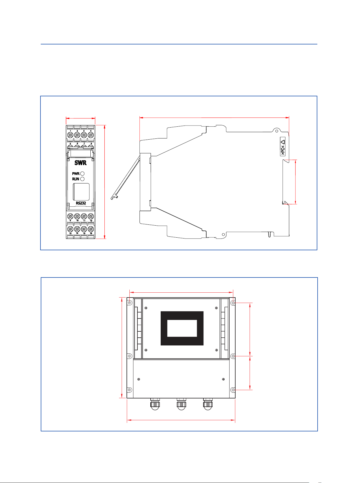
10
Fig. 9: DIN rail housing for the transmitter
Fig. 10: Field housing for the transmitter
4.4 Mounting the transmitter
•The entire transmitter can be installed at a maximum distance of 300 m from the sensor.
The housing is prepared for installation on a DIN rail according to DIN EN 60715 TH35.
23
90
118
35
90 120
244
254
237
Table of contents
Other SWR Measuring Instrument manuals


