Soil Instruments Digital Inclinometer Pro User manual

1
Soil Instruments Limited has an ongoing policy of design review and reserves the right to amend these specications without notice.
Man251 - Digital Inclinometer Pro – MN1114 – Rev1.2.5
Man 251
Digital
Inclinometer Pro
User Manual
2
QUESTION
What’s this manual about?
This manual tells you about the Digital Inclinometer Pro and
how to use it to take readings of lateral deections.
Who does this apply to?
Installers, eld engineers and technicians using the Digital
Inclinometer Pro.

3
Welcome!
Thank you for choosing the Digital Inclinometer Pro.
This manual has been written to help you utilise all of
the functions of the Digital Inclinometer Pro.
Please read this manual thoroughly before use to help
avoid any problems and keep it handy when using the Digital
Inclinometer Pro.
Digital Inclinometer Pro.
The Digital Inclinometer Pro comprises a biaxial probe, cable
reel and a rugged Tablet supplied with ‘In-Port Pro’ application.
The inclinometer probe measures lateral deections using
MEMS sensors, enabling the system to take highly accurate
and repeatable readings whilst transferring the measurements
via a digital signal for interference-free data transmission.
The system incorporates Bluetooth technology for
communicating from the inclinometer reel to the Tablet,
oering a complete cable free data transmitting system with
no connectors to corrode or break.
The graduated cable is constructed with Kevlar, making it very
strong and durable whilst remaining lightweight and consists
of a metal cable marker system which, when used in
conjunction with the cable gate, provides highly accurate and
repeatable depth control.
With all these combined design features, the Digital
Inclinometer Pro is a robust, eective and highly accurate
system that is light, compact and easy to operate in any
site environment.

4
Contents
OVERVIEW & INTRODUCTION 6
Important Information 6
Product Changes 6
Warrenty 6
Disposal 6
System Components - Things You Need to Know 7
About Inclinometers 7
System Components 7
The Digital inclinometer Pro 8
Measurement Axis 8
Control Cable 9
Handling The Probe 9
Cable Gate 9
Bluetooth Reel 9
Front Panel LED’s 10
Power Button & Power LED 10
Comms Ready/Bluetooth LED 10
Battery LED 10
QUICK START GUIDE 11
Using The Digital Inclinometer Pro 11
Before You Go To Site 11
Charging The Battery 11
Detachable inclinometer Pro Connection 11
In-Port Pro App Overview 12
In-Port Pro Software 12
Action Bar 12
Adding An Inclinometer 13
The Inclinometer List 13
Adding An Inclinometer 13
Fields On The Inclinometer Form 14
Recording Inclinometer Surveys 15
A-Grooves 15
Orientation Of Probes 16
The Survey Screen 17
0-Pass Screen 17
180-Pass Screen 17
Survey Buttons 18
Changing The Active Depth 18
Halting a Survey 19
Resuming An Interrupted Survey 19
Recording The Survey 20

5
Recording The 0-Pass 22
Recording The 180-Pass 26
DETAILED SOFTWARE GUIDE 30
Plotting Inclinometer Surveys 30
Introduction 30
Checksums 30
Change From Initial 30
Change From Last 30
Prole 30
View Data 30
Advanced Borehole Features 31
Autorun (Hands-Free Mode) 31
QR Code Feature 32
Sending Data Files To a PC 33
USB Transfers 33
Email Transfers 35
Setting Up Email Recipients 35
Emailing Files 36
Dropbox Transfers 37
Sending Files To Dropbox 37
Options Menu 39
Options List 39
Survey Control 40
Technical Details 41
Reading Units 41
Files and Folders 41
File Management 41
MAINTENANCE GUIDE 42
Maintaining the Digital Inclinometer Pro System 42
Routine Maintenance 42
Cable Maintenance 42
Probe Inspection and Maintenance 43
Cable Inspection and Maintenance 43
APPENDICES 44
Appendix A - Data Download Format and Manual Data Reduction 44
Appendix B 45
Checksums 45
Calibration 45
Appendix C – Frequently Asked Questions 46
Appendix D – CE Declaration 47
PRECISELY MEASURED
instrumentation and monitoring

6
OVERVIEW & INTRODUCTION
Important information
The following symbols are used throughout the manual
PRODUCT
CHANGES
WARRANTY
DISPOSAL
Failure to observe the warning may result in injury, product
malfunction, unexpected readings, loss of data or damage to the
product that may invalidate its warranty.
Soil Instruments has an on-going policy of design review and reserves
the right to amend the design of their product and this instruction
manual without notice.
Refer to our terms and conditions of sale for warranty information.
The batteries are a consumable item and are excluded from
the warranty.
Products marked with the symbol are subject to the following
disposal rules in European countries:
• This product is designated for separate collection at an
appropriate collection point
• Do not dispose of as household waste
• For more information, contact Soil Instruments or the local
authority in charge of waste management.
WEE/DE3326WV
IMPORTANT
INFORMATION
QUESTION
WARNING TIP
TIP
Tips give additional information that may be helpful when using the
Digital Inclinometer Pro.
WARNING

7
Cable Marker
Accessory Carry Case
Waterproof Moulded Connection
Kevlar Cable
Cable Reel
Tablet
Moulded Handle
Wheel Assembly Inclinometer Probe
ABOUT
INCLINOMETERS
An inclinometer system includes inclinometer casing, a traversing
probe, control cable, and tablet.
Inclinometer casing is permanently installed in a near-vertical borehole
that passes through a zone of suspected movement. The probe, cable,
and tablet are used to survey the casing.
The rst survey establishes the baseline prole of the installed casing.
Subsequent surveys will reveal changes in the prole if ground
movement has occurred. Plotting these changes reveals the rate, depth,
and magnitude of ground movement.
SYSTEM
COMPONENTS
The Digital Inclinometer Pro system includes an inclinometer probe,
Cable, a Bluetooth reel, a cable gate, and an In-Port Pro app that runs on
the supplied Tablet.
Cable Gate
Things You Need to Know About the Digital Inclinometer Pro
System Description
8
THE DIGITAL
INCLINOMETER
PRO
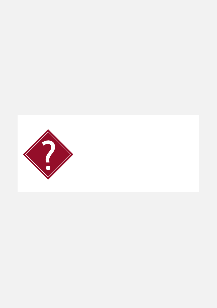
The Digital Inclinmeter Pro is supplied in metric and English versions.
The metric version has a gauge length of 0.5m. The English version has a
gauge length of 2 feet. A + mark is engraved on the body of the probe.
This is used to orient the probe during a survey.
MEASURMENT
AXIS
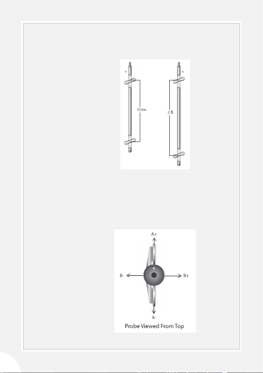
There are two MEMS tilt sensors inside the probe. The A-axis sensor
measures tilt in the plane of the wheels. The B-axis sensor measures tilt
in the plane perpendicular to the wheels.
When the top of the probe is tilted in the + direction, tilt values are
positive, and when the probe is tilted in the - direction, tilt values are
negative.

9
PROBE CABLE The cable is used to control the depth of the inclinometer probe. It also
conducts power and data between probe and reel.
• Metric probe cables have half-meter graduations with labels every
meter. The rst graduation is 0.5 meters from the top wheels of
the probe.
• English probe cables two-foot graduations with labels every
four feet. The rst graduation is 2 feet from the top wheels of the
probe.
How to negate plotting errors
The Digital Inclinometer Pro system displays readings as mm or inches
of tilt, and this reading applies at the depth of the top wheel set pivot
point.
The Soil Instruments standard inclinometer along with inclinometer
systems from some other manufacturers use cable markers that are
spaced from the middle of the probe (mid-probe datum systems), but
this has some unexpected eects when the readings are plotted.
Digital Inclinometer Pro system has been designed to negate these
plotting errors.
If you are using your Digital Inclinometer Pro system in new boreholes
then the following does not apply.
However if you use a Digital Inclinometer Pro in a Borehole that has
previously been read using a mid-probe datum inclinometer you will
see anomalies in the data plots when comparing the previous borehole
runs with the new borehole runs.
There are a number of options of how to negate these
anomalies:
Option 1
• Take a new datum set and exclude the previous data runs from
the plot.
Option 2
• Add a 250mm section of casing to the borehole which will
position the new probe in the same positions in the borehole as
the original probe.
• the 250mm value may need adjusting for dierences in cable
support gates.
IMPORTANT
INFORMATION

10
HANDLING THE
PROBE
The inclinometer probe is a sensitive measuring intrument. handle it
with care.
• When you insert the probe into the casing, cup the wheels with
your hands to compress the springs and allow a smooth insertion.
• When you lower the probe into the borehole, do not allow it to
strike the bottom.
• When you withdraw the probe from the casing, again cup the
wheels with your hands to prevent them from snapping out.
• When you rotate the probe, keep it upright and perform the
rotation smoothly.
• The probe is rated for temperatures from -20 to 70°C (-4 to 158°F).
Avoid using the probe in temperatures outside this range.
During the survey, successive
cable graduations are locked
into the cable gate to hold
the probe steady for readings.
The cable gate ts three
diameters of casing: 85, 70,
and 48 mm (3.34, 2.75, and
1.9 inch).
CABLE GATE The cable gate is pushed onto the top of the inclinometer casing to
serve as the reference for the depth graduations.
The Bluetooth reel provides a convenient way to carry the probe,
control cable, and cable gate. The reel transmits commands and data
between the tablet and the probe. A battery pack inside the reel powers
both the reel and the probe.
BLUETOOTH REEL
Option 3
• Use the Depth Index adjustment feature in In-Prole to reposition
the previous data sets.
• See article Using In-Prole Depth Index Correction.
Table of contents


