SignalFire Modbus-Stick User manual
Rev 5.8 SignalFire Telemetry
1
Interface Manual
Modbus-Stick
SignalFire Number: MBS-CBBL
The SignalFire Modbus-in-a-Stick has the following features:
-RS485 connection to Modbus devices (RS232 Modbus interface can be special ordered)
-Wide range DC power input. 6 to 36VDC
-Configurable check-in period and network address
-Configurable Modbus register polling and/or transparent register mode
-Modbus register writes to remote nodes
-Full time mesh node can forward messages from other SignalFire devices including sleeping
nodes
-Sends data to SignalFire Modbus Gateway
-Integrated 500mW FHSS 900MHz ISM band radio and high gain antenna
-AES 128bit Encryption

Rev 5.8 SignalFire Telemetry
2
Connections
The Modbus-in-a-Stick is supplied with a 6 conductor cable. The connections are as
follows:
Wire Color
Connection
RED
Positive Power (6 to 36 VDC)
BLACK
Ground
GREEN
RS-485 “A”, 9600 Baud (default)
BROWN
RS-485 “B”, 9600 Baud (default)
ORANGE
RS-232 Debug/Programming TX, 9600 Baud
YELLOW
RS-232 Debug/Programming RX, 9600 Baud
When configured as a RS232 Modbus stick (base stamped “232”), Green = Stick RX, Brown = Stick TX.
Ground must also be connected when using RS232 interface.
Status LED
The Modbus-in-a-Stick has one LED available for field diagnostics.
LED
Description
Slow Flash (3 second pause)
System is running and in communication with radio network
Fast Flash (0.5 second pause)
System is running but no network found
Solid On
System Fault, needs service

Rev 5.8 SignalFire Telemetry
3
Operation
The Modbus-in-a-Stick supports two modes of operation, a preconfigured register set,
and an automatic scanning “transparent” mode. The Modbus stick can be used in either
mode or a combination depending on the system requirements.
Pre-Configured Register Set Mode
This mode of operation is most useful for large data sets, and frequent polling of a set register map.
This mode requires that the Modbus Stick be configured with the register map with the configuration
utility at the time of installation.
In this mode the pre-configured set of registers is automatically read from the Modbus sensor device
and forwarded to the Modbus gateway on a pre-defined schedule (1 minute to 5 minutes is typical).
The register data is then buffered in the gateway and is available to be read by the RTU at any time.
This is the most efficient and robust mode of operation.
Transparent Modbus Mode (version Modbus_r38 and Gateway version 7.37 and later only)
This mode requires no Modbus setup at the Modbus Stick, and can be used to smaller number of
registers that only need to be read or written infrequently. All standard Modbus opcodes are
supported.
Upon initial power-up the Modbus Stick will automatically poll all slave IDs (1-240) to discover
attached devices. Any devices found will be reported to the gateway so that a wireless link will exist to
the Modbus device. This scan is automatically repeated every hour in the event that an additional
device is added to the bus. The scan may also be initiated from the Modbus Stick’s debug port, or
remotely from the Modbus Gateway. See the Modbus Gateway manual for register details.
Alternatively one or more Modbus Program steps can be entered for a given slave ID so that the Slave
ID will be known to the Gateway.
When the RTU polls the gateway for a Modbus register, if the register is buffered (meaning it was pre-
configured) the buffered value is returned. If the register value is not buffered, but the Modbus slave
ID is known, the request is forwarded over the SignalFire wireless network to the Modbus sensor, the
response is forwarded back to the gateway and delivered to the RTU. Due to the multi-hop wireless
network, latency will be introduced. It is required that the RTU’s timeout be on the order of 5-10
seconds to allow for maximum possible networks delays. This limits the effective amount of data that
can be pulled.
Rev 5.8 SignalFire Telemetry
4
Setup
The Modbus-in-a-Stick requires initial configuration over the debug port. This is done
using the SignalFire Toolkit PC application to configure the device over a serial port.
The following items must be configured:
-Network Selection / encryption settings
-Check-in Period Selection (Pre-Configured Register set mode only)
-Modbus Slave ID and register configuration (Pre-Configured Register set mode only)
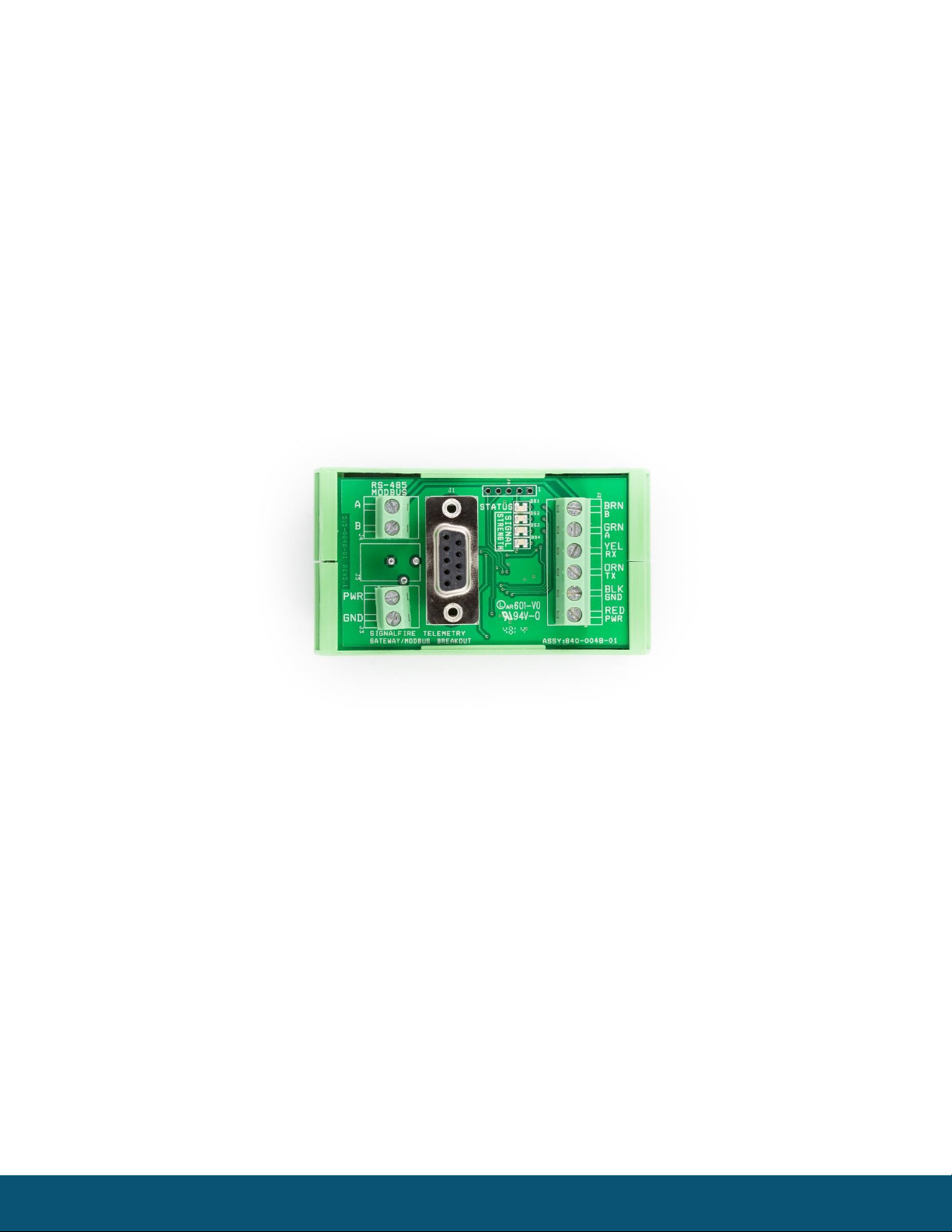
Breakout Board
The breakout board above is included with the standard Modbus Stick and provides for easy wiring
and a DIN rail mount. PWR and GND can be wired in to the breakout board, as well as RS485 A/B.
The STATUS LED will blink at 1 sec when offline, and 3 sec when connected. The Signal Strength LEDs
give a relative RSSI reading. The breakout board also has a built in DB9 RS232 port for easy
configuration via the SignalFire Toolkit.
Rev 5.8 SignalFire Telemetry
5
Configuration
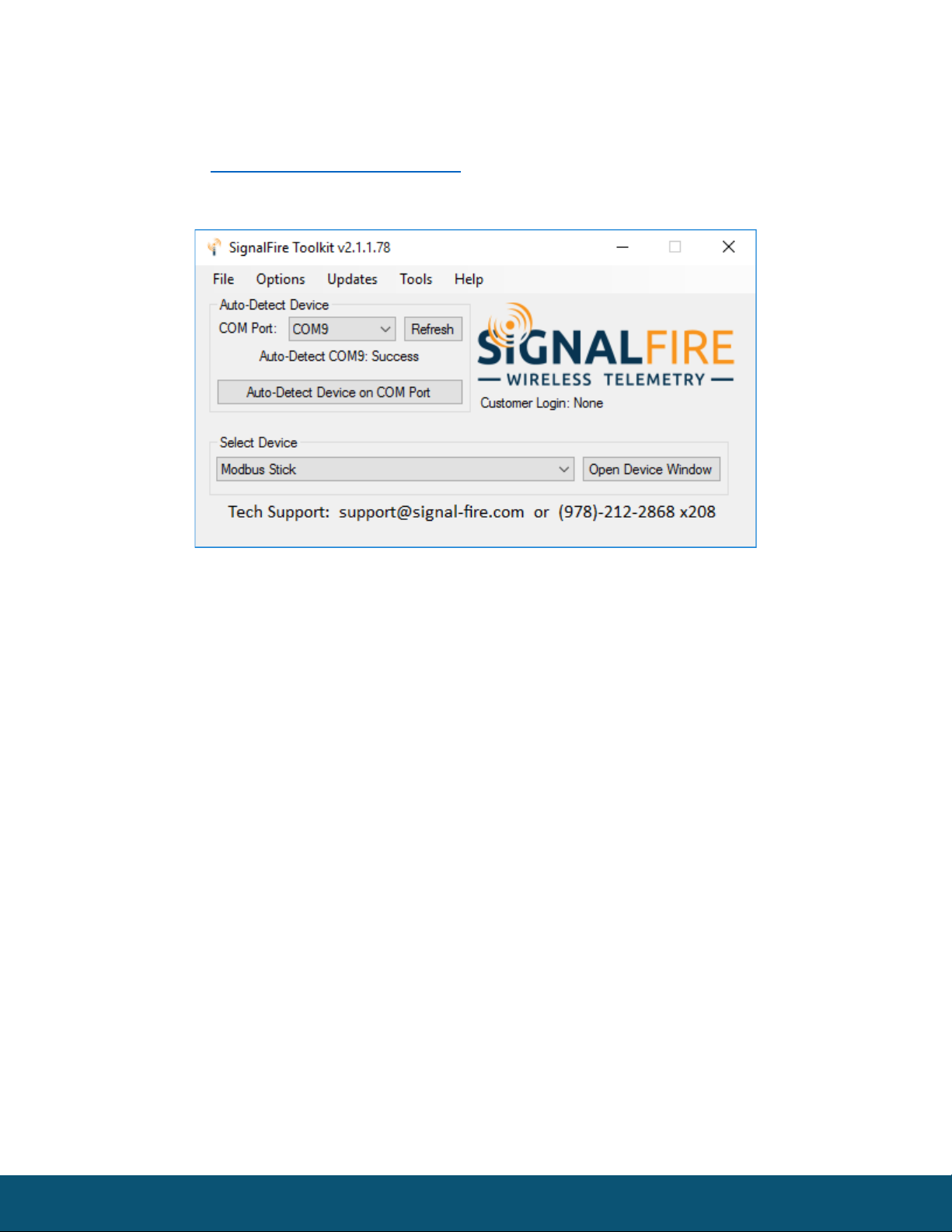
To begin configuration, open the SignalFire Toolkit. The SignalFire Toolkit application can
be downloaded at www.signal-fire.com/customer. After installation, launch the software
and the main toolkit window will open:
Select the COM port associated with the Modbus Stick and click “Auto-Detect Device on COM Port.”
This will open the device configuration window, where all device settings can be configured.
Rev 5.8 SignalFire Telemetry
6
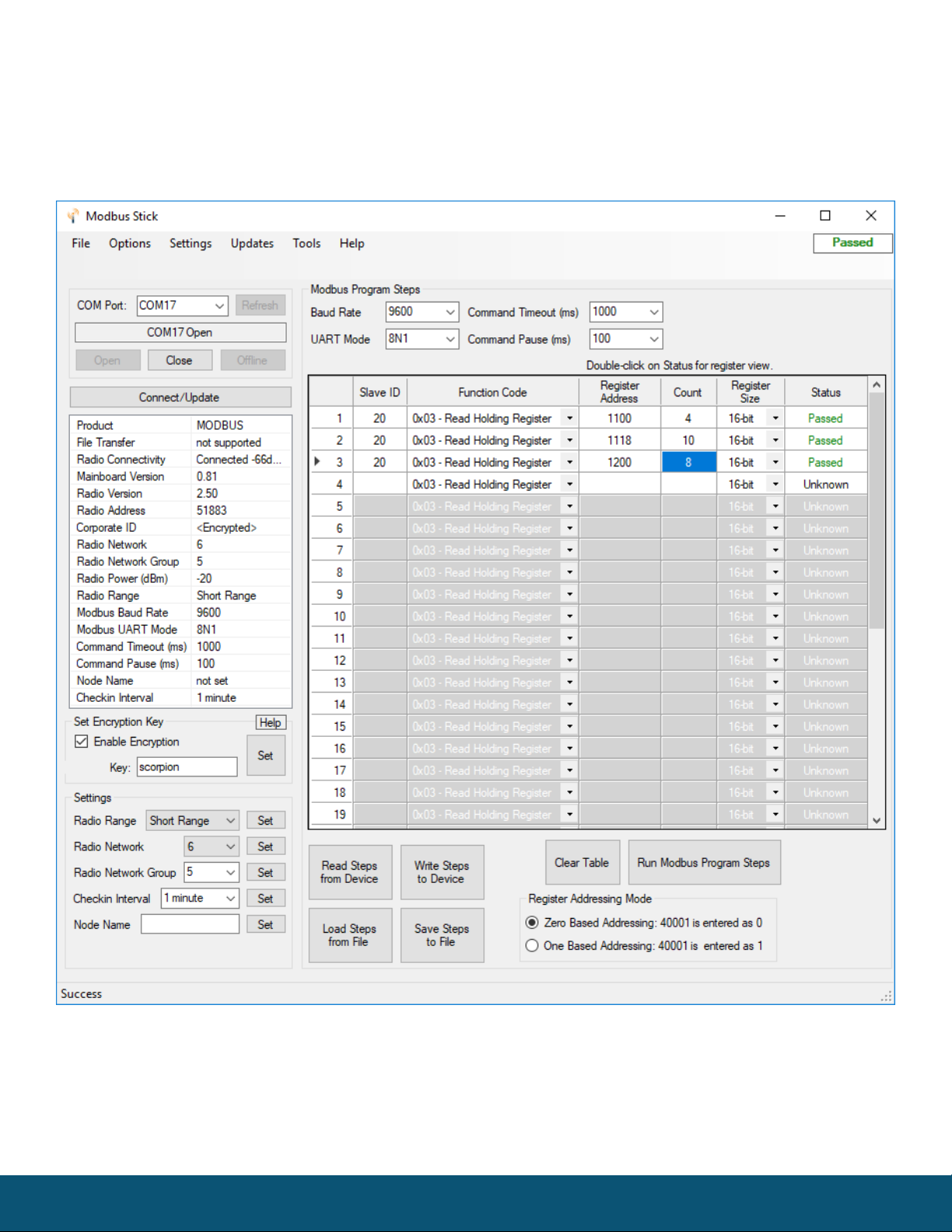
Modbus-in-a-Stick configuration window
Rev 5.8 SignalFire Telemetry
7
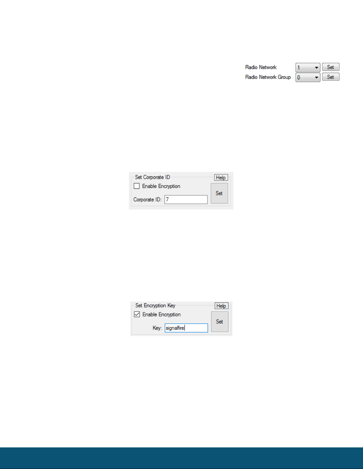
Network Setting
The network address can be used to create separate networks using multiple gateways
(that are in close proximity with one another). The network is set using the SignalFire
Toolkit. The Network Group setting is used when more than 8
networks are needed. Both the network and network group must
match those of the gateway to communicate.
Encryption
Starting with Modbus-Stick version r72, it is possible to encrypt over-the-air transmissions to prevent
tampering. Encryption keys replace the Corporate ID system, so it is important that all devices
connected to a Gateway have the same encryption key as well as network and network group number.
To set up a Modbus-Stick to use encryption, click the checkbox labeled Enable Encryption inside the
Set Corporate ID box:
The encryption key box. For more details, click the Help button.
The box will then change into a Set Encryption Key box, and it will prompt instead for the encryption
key you would like to use. Note that keys may not contain spaces or angle brackets. Enter it and then
press Set. This will cause the Modbus-Stick to drop its network, and only attempt to join networks that
use the same encryption key. If you are setting up a new network, you will need to set the encryption
key on all of your devices. If you are adding a Modbus-Stick to a legacy network, you can simply set the
Corporate ID without clicking the Enable Encryption box, and it will remain compatible with the older
system.
Setting the encryption key.
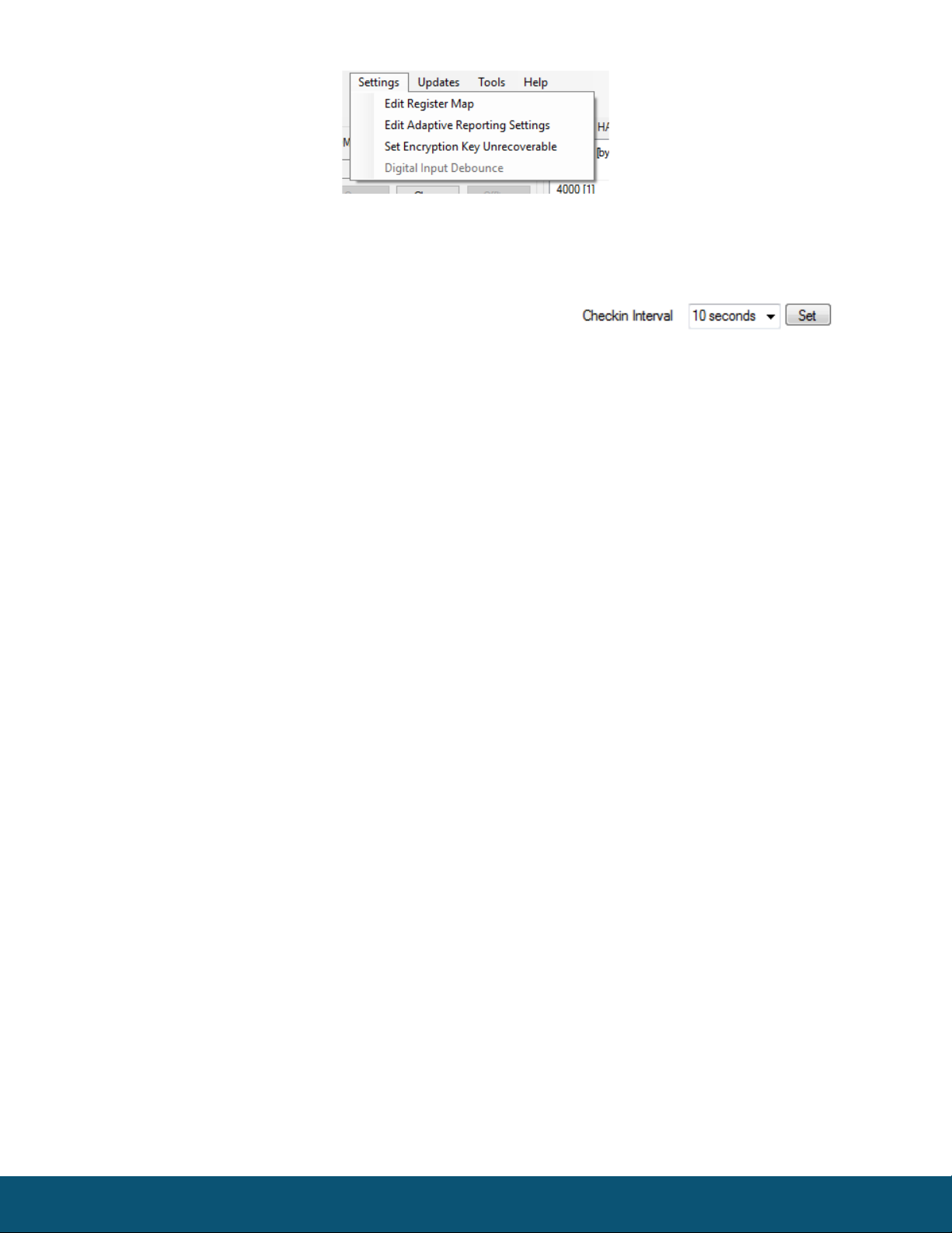
It is also possible to hide your encryption key so it cannot be read. This is the most secure option, but
if you forget your key, there is no way to recover it – you have to reset the key on every device on its
network. To enable this option, select Set Encryption Key Unrecoverable under the Settings menu.
Rev 5.8 SignalFire Telemetry
8
Setting the encryption key to be unrecoverable.
System Check-In Period
This setting controls how often the node will read the Modbus device and forward the register data to
the gateway.
Rev 5.8 SignalFire Telemetry
9
RS-485 Modbus Communication
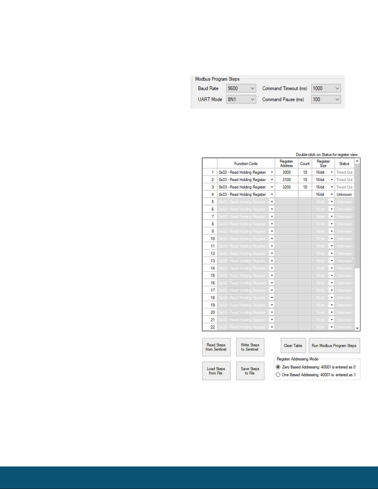
Communication Settings
The Sentinel Modbus needs to have its serial RS-485 parameters set to match the device
it’s communicating with. Default settings are a baud rate of 9,600bits/s, UART mode 8N1
(8 data bits, No parity bit, 1 stop bit), command
timeout of 1000ms, and command pause of
100ms. This should be sufficient for most devices,
but check your device’s datasheet to confirm.
Note that the Gateway and Sentinel’s RS-485 settings are unrelated and do not need to match.
Modbus Program Steps Configuration
The register set to poll on each check-in must be
defined using program steps. The Sentinel Modbus
can have up to 34 program steps. A program step
consists of a function code, starting address,
number of consecutive registers, and register size.
Possible function codes are:
0x01: Read discrete output (limit: 1 coil)
0x02: Read discrete input (limit: 1 coil)
0x03: Read holding register
0x04: Read input register
0x05: Write discrete output
Click Read Steps from Sentinel to view the current
program steps in the table. To add a new program
step, fill in the next empty line. To delete a step,
click on the line number and press the Delete key.
Lines can also be copy/cut and pasted. Once all the
desired program steps have been entered, click
Write Steps to Sentinel to save the changes.
The Slave ID should match the ID of the connected
Modbus device. Make sure that there are no duplicate Slave IDs in a given network; the gateway will
only cache one set of data for each Slave ID, so the duplicate will be overwritten.
The register address entered is subtracted by the offset in the Register Addressing Mode. The offset
can be 0 or 1. For example, with One Based Addressing, a holding register of address 3990 should be
entered as function code 0x03, address 3991. Keep in mind that one 32-bit floating point register
Rev 5.8 SignalFire Telemetry
10
should be read as two 16-bit registers. The register size should be changed to 32-bit
only if ENRON registers are being used.
Modbus Program Steps Configuration (Legacy)
If using ToolKit version 2.2.18 or earlier, the menu to enter program steps will be
different.
Click Read Current Program Steps from Device to view the current program steps in the table. They
can then be deleted or re-ordered using the buttons to the right of the table. To add a new program
step, fill in the 4 boxes at the bottom, and click Add New Program Step. If the step is valid, it will be
added to the table. Finally, click Write New Program Steps to Device to save the changes.
The Slave ID should match the ID of the connected Modbus device. Make sure that there are no
duplicate slave IDs in a given network; the gateway will only cache one set of data for each Slave ID,
so the duplicate will be overwritten.
Note: In the legacy menu, the Register Addressing Mode is locked to One Based Addressing, so 3990
should be entered as 3991.
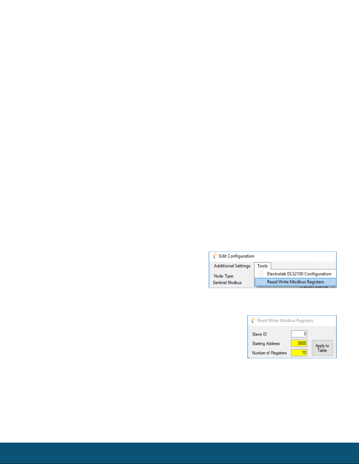
Read/Write Modbus Registers
Modbus registers of devices that have an RS-485 interface can be read and written through the
Gateway when the device is in remote configuration mode. This is useful for testing or for setting
configuration parameters in the end Modbus device. For
information on remote configuration, see the Gateway
manual. Once the Modbus remote configuration window
has been brought up, select ‘Tools’ and then ‘Read/Write
Modbus Registers.’
Create the register list by entering the Slave ID (defaults to the slave id
of the device), starting address, number of registers and click Apply to
Table. The form will populate with the number of registers starting at
the start address and a default data type of unsigned 16-bit integer.
Click ‘READ Registers’ to read the current Modbus registers from the device. The Data Type and
Register Value fields can be edited, and the changes will be highlighted. Click WRITE Registers to write
the changes to the Modbus registers in the device.
This manual suits for next models
1
Table of contents
Other SignalFire Measuring Instrument manuals


