Semtech IOT8EUSBREF-1 User manual

Smart Building
Reference Kit
User Guide
(“User Guide”)
IOT8EUSBREF-1 (EU 868)
IOT9USSBREF-1 (NA 915)
August 2019

Smart Building Reference Kit User Guide | Proprietary Information | Semtech Corporation
Welcome!
The Smart Building Reference Kit (“Kit”) is designed to provide validation of the network coverage within a
building, accelerate solution development and facilitate a portable demonstration to a wide range of stakeholders.
By moving the location of the sensors to different spots around the building, users can determine a gateway’s
range of coverage.
By relying on readily-available hardware, solution developers can focus on providing customer value through data
collection and analysis while using off-the-shelf hardware available from external suppliers.
The self-contained nature of the Kit makes it easy to set up, take down and move the network in a matter of
minutes.
All data collected in the Kit is displayed on a dashboard accessible by the user via a browser. The dashboard shows
the type of display which can be created with the data collected. The URL for the dashboard and how to locate
the log in credentials for your Kit, are explained under the Getting Started section of this User Guide.
Note: The Kit does not allow access to the underlying data directly or the ability to change the LoRaWAN-enabled
network server (LNS) to which the gateways are connected. If those are desired requirements, please contact
Semtech at [email protected].
Additionally, the user may separately access a dashboard that shows a permanent installation of a Kit inside an
office facility. This provides the user with a rich set of historical data to use in demonstrations. To access this
dashboard, log in to the following site, using the credentials below:
URL: lora-developers.semtech.com/smart-building-kit
Login: SemtechDemo1
Password: LoraWan592
The data in each dashboard is stored for a maximum of 30 days.
To provide the best user experience, we recommend visiting our LoRa® Developer Portal and downloading the
latest version of this User Guide.
https://lora-developers.semtech.com/resources/developer-kits/smart-building-kit/smart-building-kit-welcome/

Smart Building Reference Kit User Guide | Proprietary Information | Semtech Corporation
What is in the Kit?
The Kit contains the following:
5 desk sensors
2 Grid-EYE® Sensors
2 temperature/humidity sensors
2 IR blasters
5 door/window sensors
5 room occupancy sensors
1 leak sensor
2 mini-hub gateways compliant with the LoRaWAN® protocol
1 Wi-Fi to Mobile Portable Hotspot
Getting started
To begin, log in by scanning the QR code or, using Chrome as your web browser, navigate
to lora-developers.semtech.com/smart-building-kit.
Note: Your individual login credentials can either be found on the inside cover of the box,
or on the DEVEUI data sheet provided with the Kit.
Get to know your Hotspot and mini-hubs
The mini-hubs and hotspot are preconfigured to work together. The hotspot includes 1GB of free data service. If
you need more data, you will need to sign up for a cellular service plan. For plan options, see GlocalMe1.
If additional options are needed, you can add up to two nano SIM cards in the hotspot. Use a needle to pull out
the available the SIM slots and insert the SIM cards.
Note: The hotspot included in this Kit does not support SIM cards that require PIN codes.
It is important to NOT pull the battery tabs on the sensors until at least one mini-hub is functioning properly.
Failure to provide a LoRaWAN network before enabling the sensor can result in excessive battery drain.
1 GlocalMe is a registered trademark of UCLOUDLINK in Hong Kong. The GlocalMe logo and UCLOUDLINK are trademarks of UCLOUDLINK.
Figure 1: Scan to log in

Smart Building Reference Kit User Guide | Proprietary Information | Semtech Corporation
Setting-up the Kit
1. Fully charge the hotspot.
2. Once charged, press and hold the hotspot’s power button (#11) for five seconds and wait for the device to
boot
.
Figure 2:
Hotspot Buttons and Ports

Smart Building Reference Kit User Guide | Proprietary Information | Semtech Corporation
3. The hotspot will automatically log-in and connect to the GlocalMe®2 service.
4. Once the hotspot displays the Wi-Fi name and password, as illustrated in Figure 4 you can start setting-up
the mini-hubs.
2 GlocalMe is a registered trademark of UCLOUDLINK in Hong Kong. The GlocalMe logo and UCLOUDLINK are trademarks of UCLOUDLINK.
Figure 3: Automatic Logon
Figure 4: GLocal Logon Complete

Smart Building Reference Kit User Guide | Proprietary Information | Semtech Corporation
5. Remove the cover plate on the first mini-hub. If necessary, attach the power adapter before plugging-in the
mini-hub to a wall socket as shown in Figure 5.
6. You will know the mini-hub is connected to the hotspot when the light on top turns green as shown in
Figure 6
Setting-up the sensors
In this Kit, we are monitoring room or desk use, temperature, humidity and leaks. To this end, set up the sensors
as follows.
1. Grid-EYE® Infrared Array Sensors are most effective if mounted on the ceiling or inside of a lighting fixture.
Use the adhesive tape provided with the sensor to mount it in an appropriate location in your conference
room. The Grid-EYE sensor can be used to determine the number of people occupying a room. The sensor
begins the count when motion is detected and provides an update approximately every 5 minutes
thereafter.
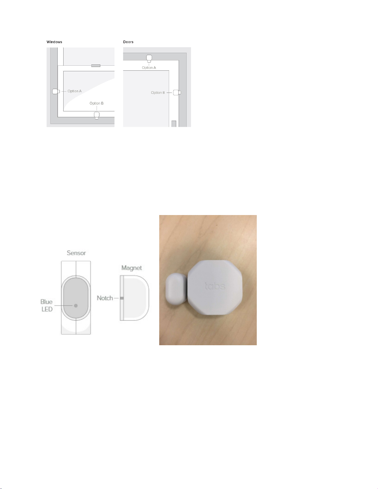
2. Window/door sensors can be mounted on either side of the window frame or door frame, as illustrated in
Figure 7.
Figure 5: Plug-in the mini-hub
Figure 6: Mini-hub connected to hotspot
Smart Building Reference Kit User Guide | Proprietary Information | Semtech Corporation
Note: The maximum allowable gap between a sensor and the corresponding magnet is 1 cm. Be sure to
align the sensor side with the blue LED to the magnet face with the notch, as illustrated in Figure 8.
The door/window sensor will provide an indication of whether the door or window is open or closed.
Figure 7: Window and Door Sensor Placement
Figure 8: Door/Window Sensor and Magnet Alignment

Smart Building Reference Kit User Guide | Proprietary Information | Semtech Corporation
3. The desk occupancy sensor may be mounted on the underside of a desk using the double-sided tape
provided. For best results, mount the sensor horizontally approximately 25 cm from the front edge of the
desk, as shown in Figure 9.
The desk occupancy sensor may take up to 5 minutes to appear on the dashboard when first connected.
Figure 9: Desk Occupancy Sensor
Note: The sensor will send a message when motion is detected. No additional messages will be sent as long
as motion is detected anytime within the next 5 minutes. Only after detecting no motion during a 5 minute
period will it send a message indicating that the desk is unoccupied. Therefore, changes in condition may not
be reflected in the dashboard immediately.
The daily desk occupancy statistics shown on the dashboard are only calculated once a day, at midnight.
4. To detect movement in a room, place the room occupancy sensor on a flat surface, such as a table or
bookshelf. The room occupancy sensor behaves much like the desk occupancy sensor in terms of the 5-
minute behaviour.
As with desk occupancy statistics, room occupancy statistics are only calculated for the preceding 24-hour
period commencing at midnight each day.
The room occupancy sensor may take up to 5 minutes to appear on the dashboard when first connected.
5. To detect the temperature and humidity in the room, place the temperature/humidity sensor anywhere in
the room. To mitigate momentary changes in temperature due to opening a door or window, best practice
is to place this sensor away from doors and windows.
6. The IR blaster can control wall-mounted HVAC systems, heaters, televisions and any other electronic
devices that use an infrared signal with a known Pronto code. A list of codes can be found at either of these
two websites:
http://irdb.tk/

Smart Building Reference Kit User Guide | Proprietary Information | Semtech Corporation
http://www.remotecentral.com/cgi-bin/codes/
To use, place the IR blaster so that it is three to five feet from the item to be controlled, facing the item’s
infrared receiver.
Figure 10: Face of the IR blaster
Next, navigate on your browser to your Kit’s dashboard. Click on the Environment tab on the left hand side.
You will be presented with a screen which includes a place where the Pronto code can be entered as shown
in Figure 11.
Figure 11: Entering Pronto codes for the IR blaster
7. For information about how to remove or replace the battery in any of the devices, scan the QR code below,
or use the Chrome web browser to navigate to https://qrgo.page.link/iWxb.
Note: Regulations require that the battery must be removed from the device when shipping or flying by air.
Alternatively, you can re-insert the plastic tabs to disrupt the battery current.
Smart Building Reference Kit User Guide | Proprietary Information | Semtech Corporation
Changing the mini-hub Wi-Fi connection
If you do not want to use the hotspot provided Wi-Fi network, you can configure the mini-hub to use another
network. To do so, follow these steps:
1. Leaving the mini-hub plugged-in, turn off the hotspot.
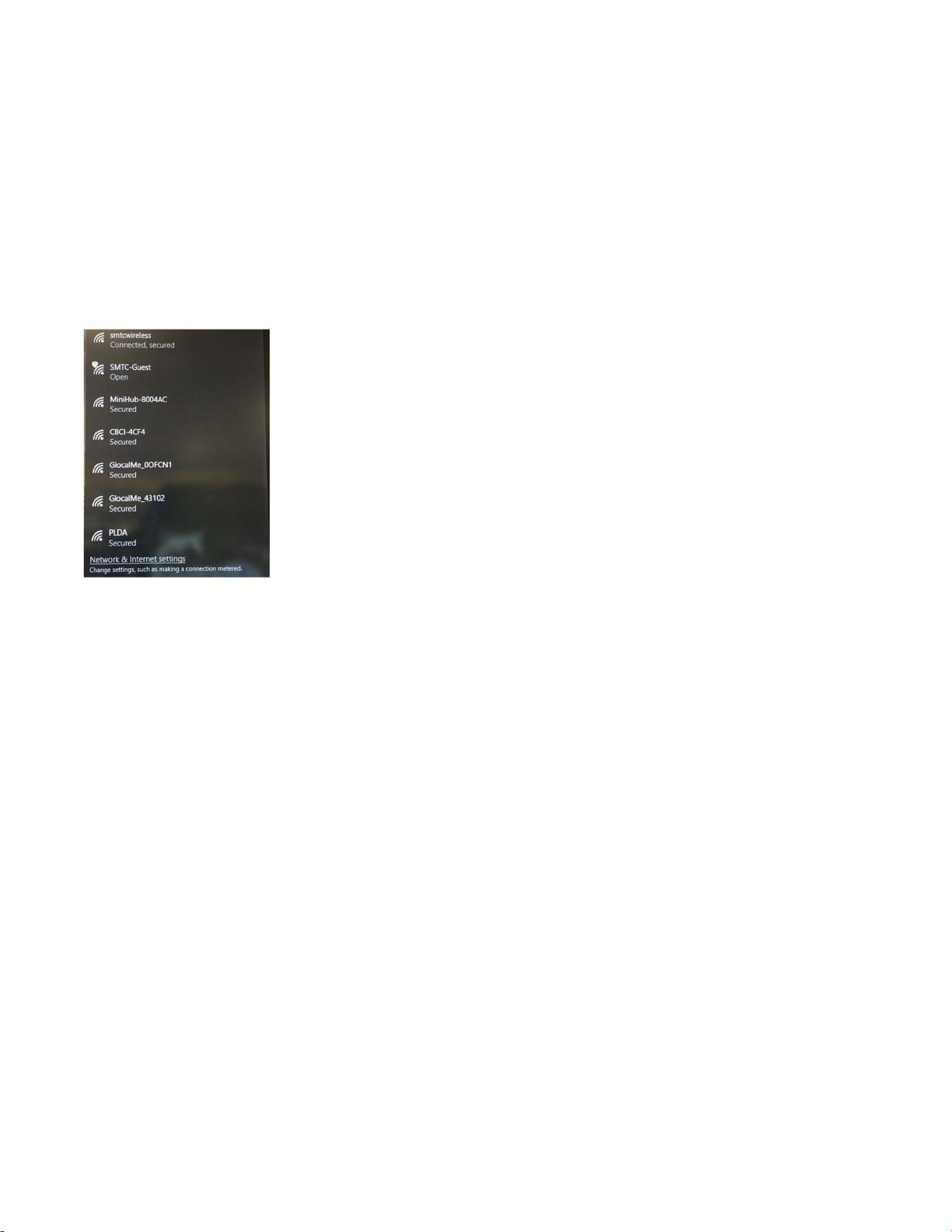
2. Using a computer, perform a network scan and select the open Wi-Fi network that starts with MiniHub-
xxxxx where xxxxx are the last 6 digits of the mini hub MAC address, as illustrated in Figure 12.
Figure 12: Mini-hub network
3. Once the computer is connected to the mini-hub, open a web browser and type 192.168.4.1 in the address
bar.
4. Edit the Wi-Fi SSID and Wi-Fi Password to reflect the new Wi-Fi network you want to connect to. Click Apply
to save your changes.
Other manuals for IOT8EUSBREF-1
1
This manual suits for next models
1
Table of contents


