Seametrics • 253.872.0284 Page 5 seametrics.com
EX800-SERIES INSTRUCTIONS
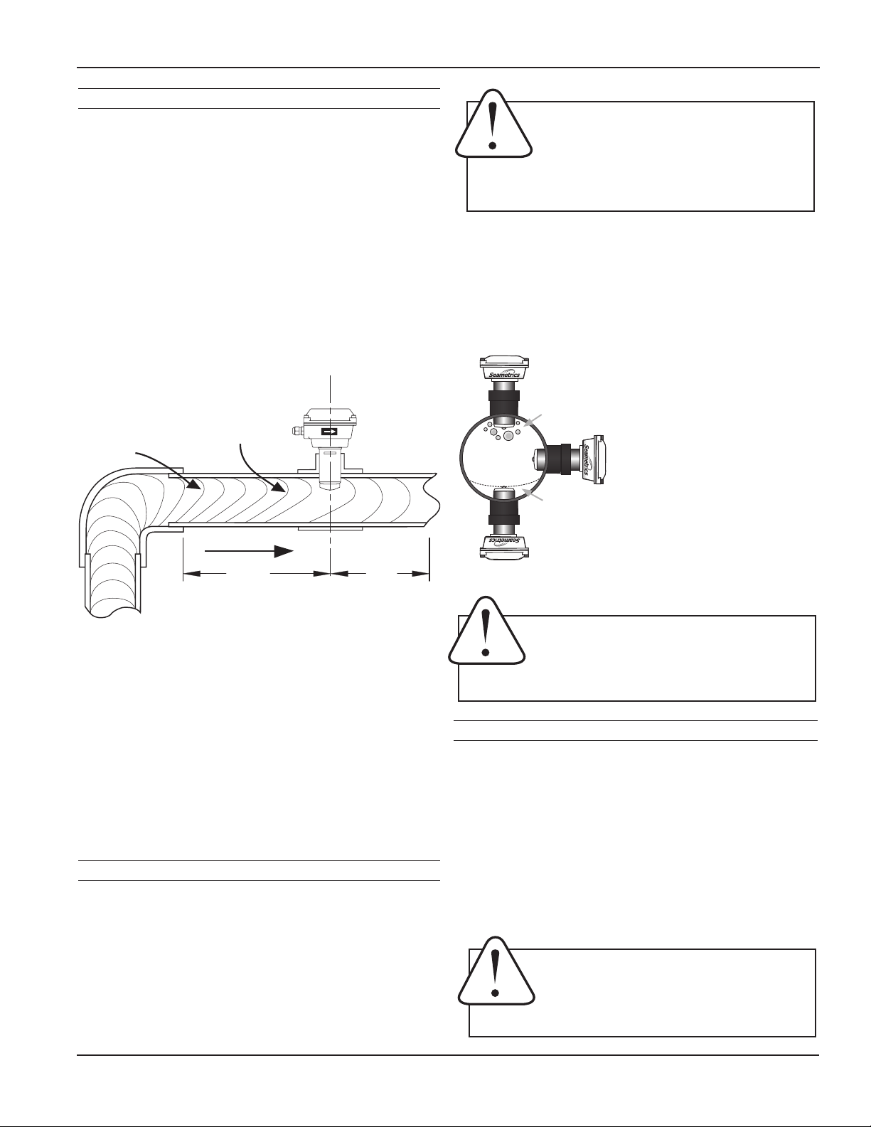
Horizontal (3 o’clock or 9 o’clock position) is the preferred
installation orientation, since it improves low-ow
performance and avoids problems with trapped air and
sediment. (See Orienting the Meter diagram below.)
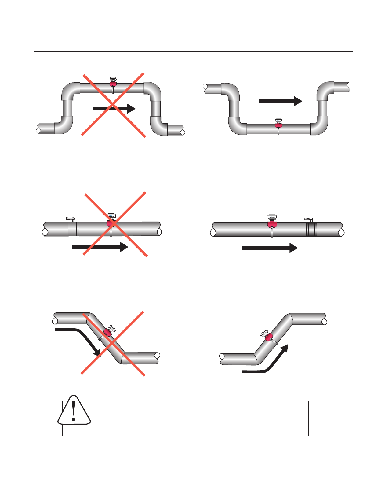
Bottom (6 o’clock), top (12 o’clock), and vertical pipe
installations are all acceptable if required by the piping
layout.
Orienting the Meter
Chemical Injection or Fertigation
When any magmeter, by any manufacturer, is used in a
chemical injection application (including fertigation), the
chemical injection point must be placed downstream of
the magmeter OR far enough upstream for complete
mixing to occur before the uid reaches the meter. When
unmixed chemical or fertilizer alternates with water passing
through the meter, the rapid changes in conductivity may
cause sudden spikes and drops in the meter’s reading,
resulting in inaccurate measurement. The magmeter will
restabilize, however, with a steady ow of uid of uniform
conductivity.
Caution: These ow sensors are not
recommended for installation downstream of a
boiler feedwater pump where installation fault
may expose the ow sensor to boiler pressure
and temperature. Maximum recommended temperature
is 130°F (Plastic), 200°F (Metal).
Fair
Unacceptable if pipe
contains air
Best
Position
Air bubbles
Sediment
Fair
Unacceptable if pipe
contains sediment
Caution: Never remove the U-clip retainer when
the pipe is under pressure. Always remove
pressure from the pipe before you attempt to
remove the meter. Removal under pressure
may result in damage or serious injury.
Caution: In chemical injection or fertigation
applications, install chemical injection point
downstream of magmeter, or far enough
upstream to allow complete mixing of uids
before the meter.
Fitting Installation
EX800-Series meters require special ttings that ensure
that the ow sensor is installed to the correct depth. The
tting must be installed in the pipeline before the meter
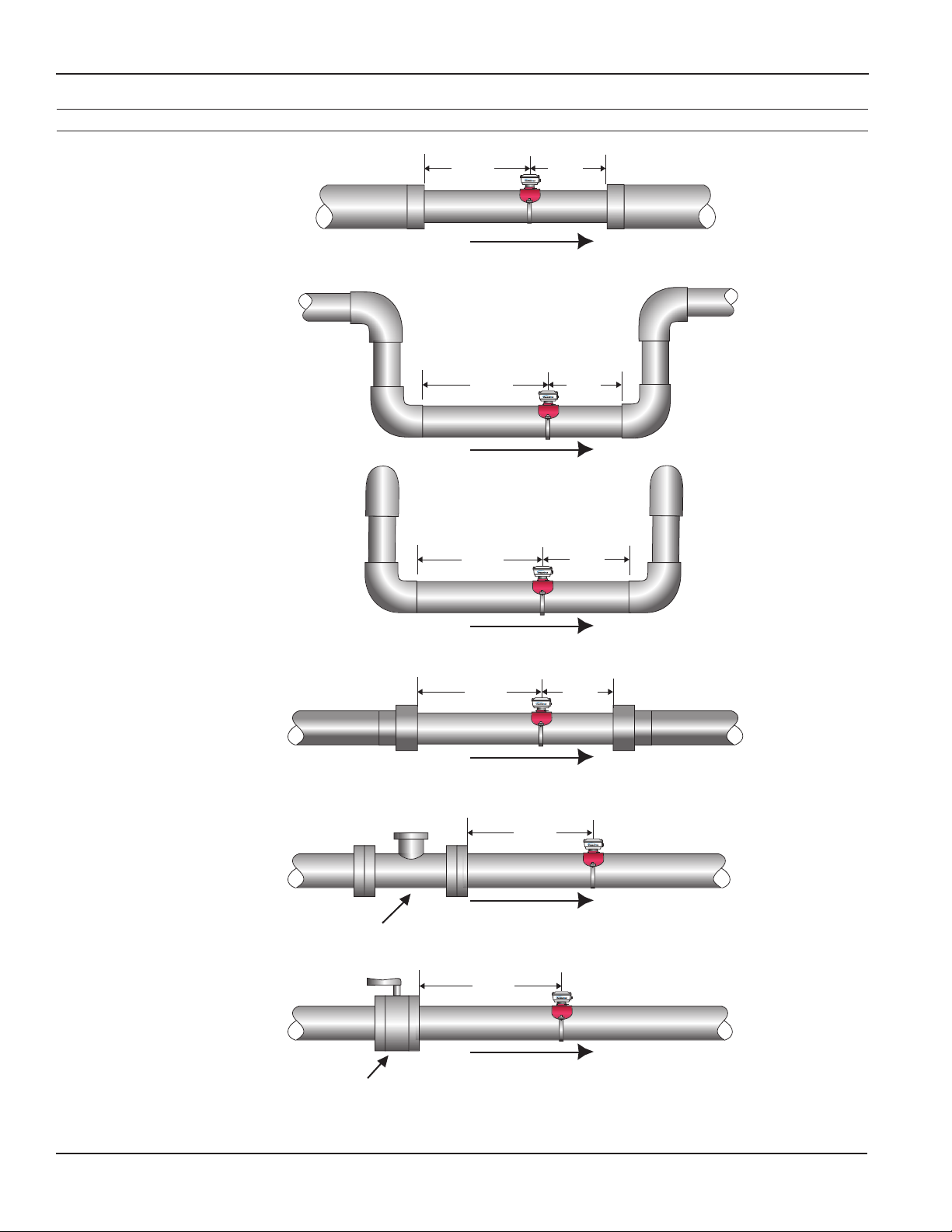
can be installed. For best results, install with at least ten
diameters of straight pipe upstream of the meter and ve
diameters downstream (or more under specic adverse
circumstances). See diagrams, next page.
If there is not enough straight run to smooth out the
turbulence caused by valves, ttings, and changes in
direction, some decrease in accuracy may result. This does
not mean that the ow meter’s reading is meaningless,
however. In some applications (control systems, valve
operation, chemical addition), a repeatable reading may
be more important than a highly accurate one.
Distorted Flows
Although EX800-Series PVC meter tees are supplied with
some straight pipe, additional straight pipe should be
added to meet straight pipe recommendations. It is not
advisable to connect a ow-disturbing device (e.g. valve or
elbow) directly to the end of these ttings.
A PVC tting is usually installed by solvent welding. The
stainless steel and brass meter ttings have female pipe
threads, requiring the appropriate male threaded ttings.
Saddle or weld ttings (3” and above) require a hole to be
cut in the pipe. Recommended hole size is 1-3/4”.
Meter Installation
After the meter tting is installed in the pipeline, the meter
can be installed in the tting. After noting the direction
of the ow arrow, press the meter into the tting as far
as it will go. Retain the meter in place by inserting the
U-clip. The clip can be installed from either side. It may
be necessary to rotate the probe back and forth slightly to
start the clip into the slots on the probe. Slide the clip in
as far as it will go.
5X
Distorted
Flow Prole
Faster Flow
Causes Meter
To Read High
10X
INSTALLATION