Samson 3930 Service manual
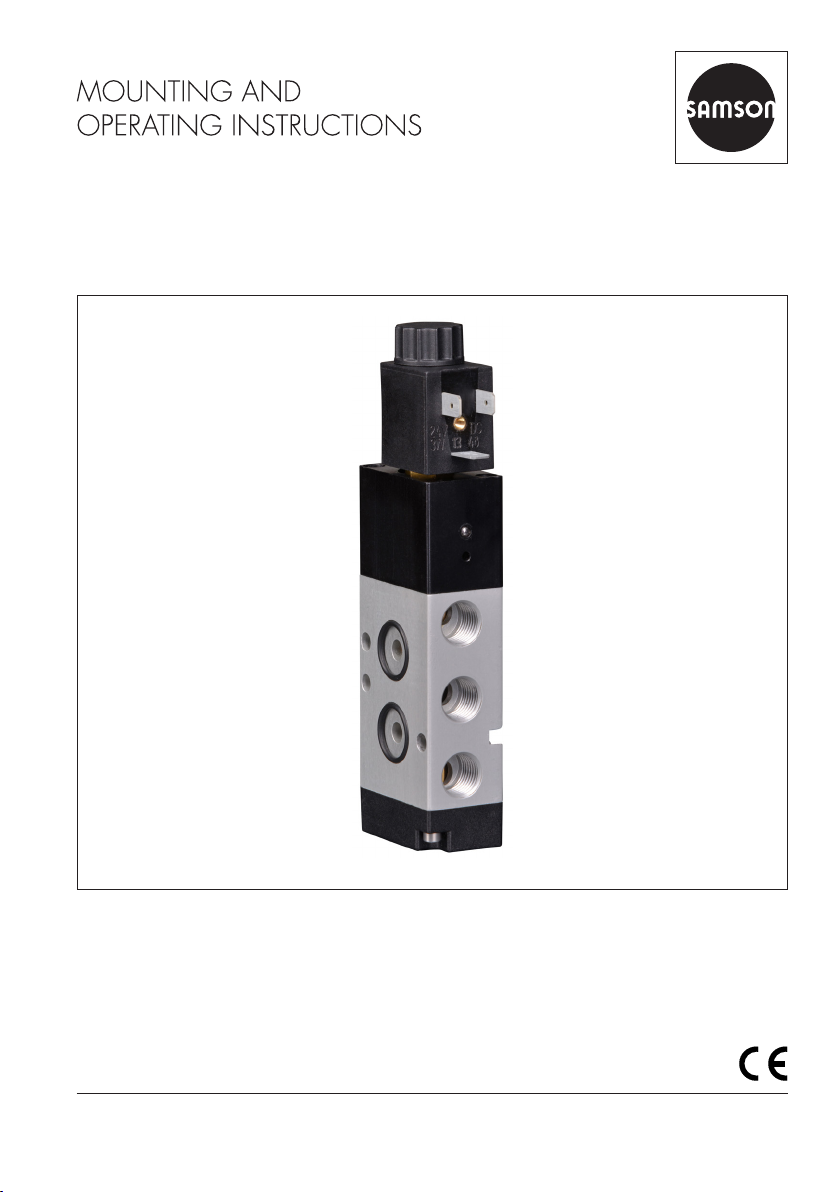
Translation of original instructions
EB 3930 EN
Edition October 2020
Type 3930 Solenoid Valve
Definition of signal words
Hazardous situations which, if not avoided,
will result in death or serious injury
Hazardous situations which, if not avoided,
could result in death or serious injury
Property damage message or malfunction
Additional information
Recommended action
DANGER
!
WARNING
!
NOTICE
!
Note
Tip
EB 3930 EN
Note on these mounting and operating instructions
These mounting and operating instructions assist you in mounting and operating the device
safely. The instructions are binding for handling SAMSON devices. The images shown in
these instructions are for illustration purposes only. The actual product may vary.
ÎFor the safe and proper use of these instructions, read them carefully and keep them for
later reference.
ÎIf you have any questions about these instructions, contact SAMSON‘s After-sales Service
(aftersalesservice@samsongroup.com).
Documents relating to the device, such as the mounting and operating
instructions, are available on our website at www.samsongroup.com >
Service & Support > Downloads > Documentation.

Contents
EB 3930 EN
1 General safety instructions.............................................................................4
1.1 Legal information...........................................................................................4
2 Markings on the device .................................................................................5
2.1 Nameplate ....................................................................................................5
2.2 Article code...................................................................................................6
3 Design and principle of operation ..................................................................7
3.1 Technical data ...............................................................................................8
3.2 Dimensions in mm..........................................................................................9
4 Mounting and start-up.................................................................................10
4.1 Mounting position........................................................................................10
4.2 Conversion from 5/2-way to 3/2-way function..............................................10
4.3 Mounting on rotary actuators........................................................................12
4.4 Attachment to linear actuators using an adapter plate.....................................13
5 Pneumatic connection ..................................................................................14
5.1 Sizing of the connecting line .........................................................................14
5.2 Compressed air quality.................................................................................14
6 Electrical connection ....................................................................................15
6.1 Sizing of the connecting line .........................................................................15
6.2 Manual override..........................................................................................15
7 Malfunctions ...............................................................................................16
8 Disposal......................................................................................................17
9 Accessories .................................................................................................17

4 EB 3930 EN
General safety instructions
1 General safety instructions
− The device is to be mounted, started up or operated only by trained and experienced
personnel familiar with the product.
According to these mounting and operating instructions, trained personnel refers to indi-
viduals who are able to judge the work they are assigned to and recognize possible dan-
gers due to their specialized training, their knowledge and experience as well as their
knowledge of the applicable standards.
− Any hazards that could be caused in the control valve by the process medium, the signal
pressure or by moving parts are to be prevented by taking appropriate precautions.
− The pilot supply pressure must not exceed the maximum permissible limit and must be
limited by a pressure reducing valve, if necessary.
− If inadmissible motions or forces are produced in the pneumatic actuator as a result of
the supply pressure, it must be restricted using a suitable supply pressure reducing sta-
tion.
− Proper shipping and storage are assumed.
1.1 Legal information
TheType3930SolenoidValvebearsaCEmarking.Thedeclarationofconformityincludes
information about the applied conformity assessment procedure.
EB 3930 EN 5
Markings on the device
2 Markings on the device
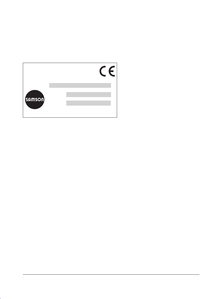
2.1 Nameplate
1 Article code
2CongurationID
3 Serial number
Solenoid valve 3930
SAMSON AG, Germany
Made in Germany
Model 3930 -
Air supply max. 10 bar/150 psi
1
Serial no.
Var.-ID
2
3
6 EB 3930 EN
Markings on the device
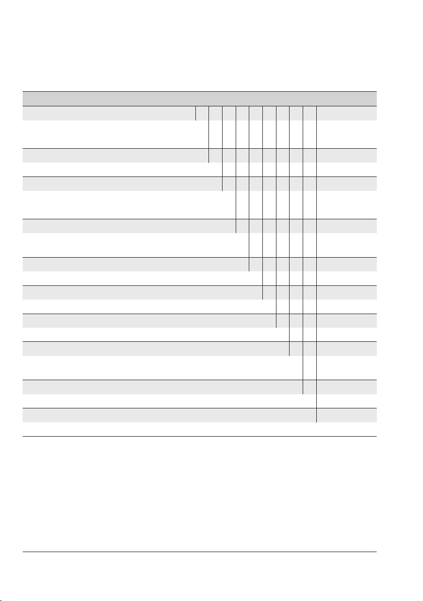
2.2 Article code
Solenoid valve Type3930- 000x3x00100000000
Nominal signal
24VDC 3
230VAC 5
Manual override
Switch (accessible using a screwdriver) 3
Switching function
3/2-way function 0
5/2-way function 1
Attachment
NAMURinterface¼“accordingtoVDI/
VDE3845 0
KVScoefcient
0.85 0
Pneumatic connection
G¼ 1
Enclosure material
Aluminum 0
Electrical connection
ConnectoraccordingtoDINEN175301-803,
typeB,3-pole(withoutcablesocket) 0
Degree of protection
IP65 0
Permissible ambient temperature
–10to+60°C 0
EB 3930 EN 7
Design and principle of operation
3 Design and principle of oper-
ation
TheType3930SolenoidValveissuitablefor
controlling pneumatic rotary actuators with
NAMURinterfaceaccordingtoVDI/
VDE3845.
The principle of operation is based on a so-
lenoid plunger system with a downstream
spool-type poppet valve. When the solenoid
coil is energized, the solenoid plunger is lift-
ed and opens the connection for the pilot
control of the poppet valve. The pressure
suppliedoverport1causestheswitchingof
the poppet valve.
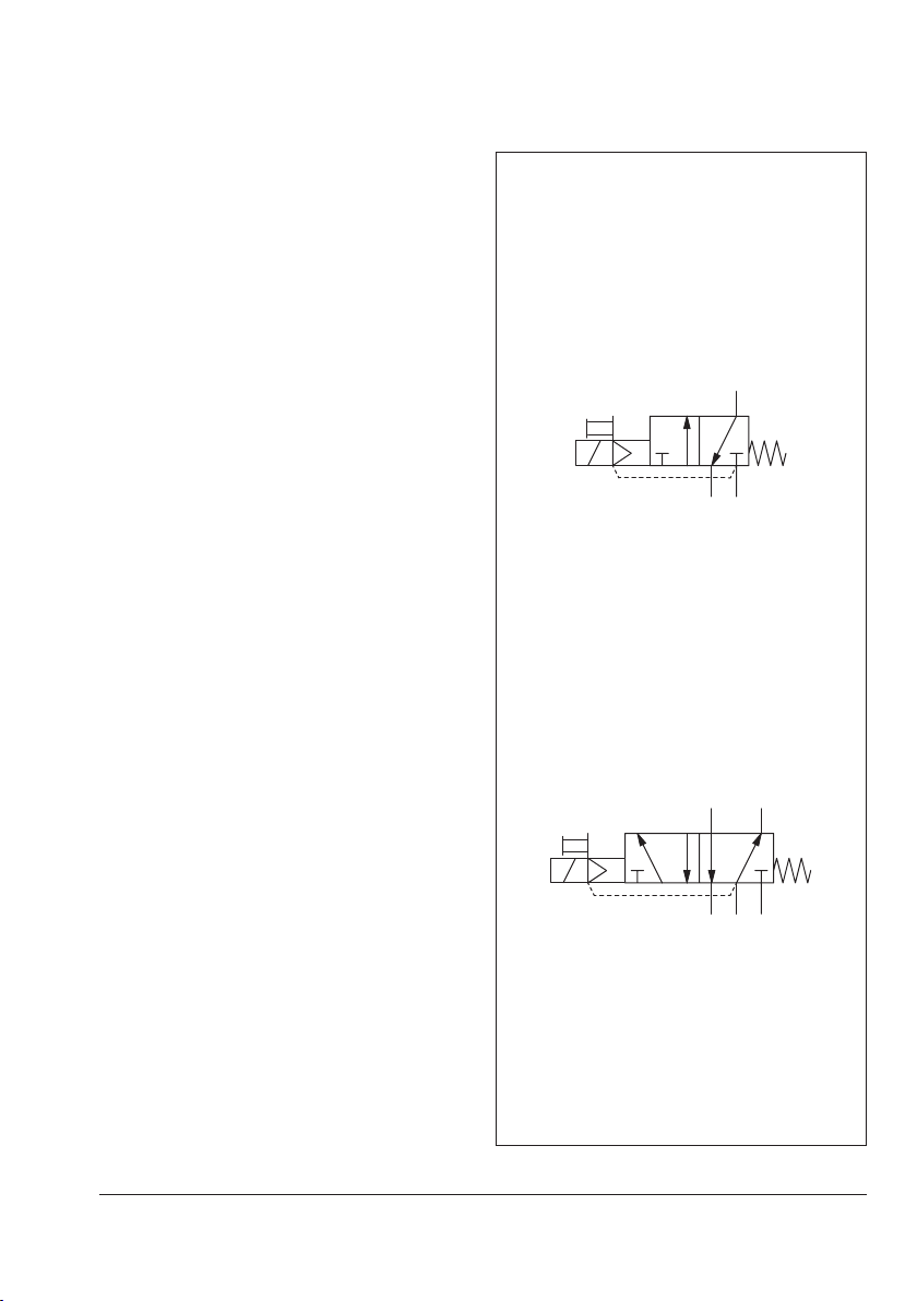
TheType3930SolenoidValveimplements
3/2-way or 5/2-way functions with KVS
0.85 (see Fig.1) depending on the version.
2
13
1
2
3
4
5
5/2-way function
3/2-way function
Fig.1: Switching functions
8 EB 3930 EN
Design and principle of operation
3.1 Technical data
General data
Design Solenoid and spool valve with return spring
Switching function 3/2 or 5/2-way function
Actuation Pilot-operated on one side
Material Enclosure: black polyamide (solenoid) and aluminum (valve body)
Internal parts: stainless steel and brass
Screws: zinc-plated steel
Short-circuit ring: copper
Gaskets: nitrile butadiene rubber
Degree of protection IP65(withmountedcablesocket)
Mounting NAMURinterface¼“accordingtoVDI/VDE3845
Mounting position Any desired position
Ambient temperature –10to+60°C
Approx. weight 0.42kg
Electric data
Nominal signal 24VDC(±10%)or230VAC(±10%),othernominalsignalsonrequest
Power consumption 3W(DC),5VA(AC)
Duty cycle 100%
Connection ConnectoraccordingtoDINEN175301-803,typeB,3-pole
Pneumatic data
Medium Instrument air (free from corrosive substances)
Medium temperature +5to+80°C
Compressed air quali-
ty according to
ISO8573-1
Max. particle size and density: Class 4 · Oil content: Class 3 · Pressure dew
point:Class3oratleast10Kbelowthelowestambienttemperaturetobeex-
pected
KVS 1) 0.85
Output signal Same as the operating pressure
Operating pressure 2.5to10bar
Connection ThreadedconnectionG¼andNAMURinterface¼“accordingtoVDI/
VDE3845
1) Theairowratewhenp1=2.4barandp2=1.0bariscalculatedusingthefollowingformula:
Q = KVS x 36.22 in m³/h.
EB 3930 EN 9
Design and principle of operation
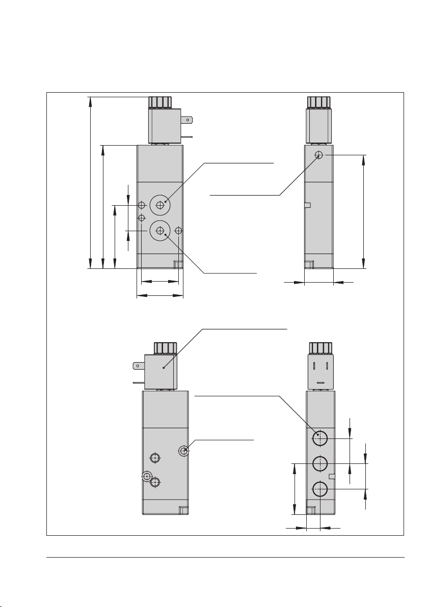
3.2 Dimensions in mm
149
107
55
24
32
40
98.5
25
12
44
22
22
NAMUR interface ¼“
accordingtoVDI/VDE3845
Manual override
Type B connector
accordingtoDINEN175301-803
Cap screw
DINENISO4762
M5x25
Connecting thread
DINENISO228/1G¼
O-ring14x1.8

10 EB 3930 EN
Mounting and start-up
4 Mounting and start-up
SAMSON solenoid valves are delivered
ready for use. In special cases, the solenoid
and valve body are delivered separately and
must be assembled on site. Proceed as fol-
lows to mount and start up the solenoid
valve.
4.1 Mounting position
Any mounting position may be used. The fol-
lowing applies concerning the installation:
ÎThe cable entries must face downward
or, in cases where this is not possible,
mount them in the horizontal position.
4.2 Conversion from 5/2-way
to 3/2-way function
The solenoid valve can be converted from a
5/2-way to a 3/2-way function or vice ver-
sa. Proceed as described below to convert
the solenoid valve (see Fig.2):
ÎUnscrew both slotted-head screws A and
B.
ÎRemove the seal and insert it into the
hole for the corresponding function (see
Fig.2).
ÎRe-insert the two slotted-head screws into
the enclosure and tighten them.
The location of the supply air connection 1 is
changed by turning the seal.
NOTICE
!
Table of contents
Other Samson Industrial Equipment manuals


