
RF Standard RS-232 User manual

RFStandard
RF Power Measurement Solutions
Doc# 6001601
Rev1.86
Page 1
RF Power Meter
USER MANUAL
for Instruments with Firmware 0.08 or higher
info@rfstandard.com www.rfstandard.com

RFStandard
RF Power Measurement Solutions
Doc# 6001601
Rev1.86
Page 2
Table of Contents
Introduction ......................................................................................................... 3
RF Power Meter Description............................................................................ 3
Items Supplied ................................................................................................. 3
Optional Accessories ....................................................................................... 3
Applicability of this User Manual ...................................................................... 3
Specifications .................................................................................................. 4
Installation ........................................................................................................... 6
RF Line Connection ......................................................................................... 6
AC Line Connection .........................................................................................
Chapter Two ......................................................................................................... 8
Operating Instructions ......................................................................................... 8
Front Panel ...................................................................................................... 8
Charging the battery ...................................................................................... 10
Performing a High Accuracy Power measurement ........................................ 11
Averaging and Pulsing Signals Operation ..................................................... 12
Serial Interface .................................................................................................. 13
Serial Communication Flow Control .............................................................. 13
Serial Cable Connector ................................................................................. 14
Command Syntax .......................................................................................... 15
USB Interface .................................................................................................... 28
Virtual COM Port Driver Installation Windows 2000 / XP ............................... 29
Virtual COM Port Driver Installation Windows / 8 / 8.1 ............................... 30
Virtual COM Port Driver Installation Windows 10 .......................................... 31
Virtual COM Port Driver Installation Macintosh.............................................. 31
Virtual COM Port Driver Installation Linux 2.40 ............................................. 31
Maintenance ..................................................................................................... 32
Calibration ..................................................................................................... 32
Battery Maintenance ...................................................................................... 32
Cleaning ........................................................................................................ 33
Troubleshooting ............................................................................................. 34
Warranty ........................................................................................................... 36
Limited Warranty ........................................................................................... 36
Chapter Seven .................................................................................................... 3
Revision History ................................................................................................ 3

RFStandard
RF Power Measurement Solutions
Doc# 6001601
Rev1.86
Page 3
Introduction
RF Power Meter escription
The RF sensor and entire processing unit are packed on a single, small
enclosure. It offers the convenience of a display (no computer required) - for bench
measurements- and RS-232 or USB connection for automated measurement systems.
The technology is patent pending and covered by intellectual property legislation.
All readings are displayed on the front panel and are also available through a
serial communication.
The RF Standard Power Meter can be powered by a wall power plug adapter,
USB interface, or internal rechargeable battery.
Items Supplied
• RF Power Meter
• 90VAC-264VAC wall plug adapter
• USB cable
• Installation USB media containing
o User Manual (this manual)
o USB software drivers
o Virtual Front Panel
o LabVIEW
®
serial drivers
• Pelican Case
®
with the manufacturer life-time warranty
Optional Accessories
- Region specific wall plug adapter
- 3-1/8EIA to 1-5/8EIA adapter (for 50kW option)
Applicability of this User Manual
- Region specific wall plug adapter
RFStandard
RF Power Measurement Solutions
Doc# 6001601
Rev1.86
Page 4
Specifications
Nominal Impedance
50Ω
Nominal Power
See the instrument front panel*
Nominal Frequency
See the instrument front panel*
MAX Power Allowable
120% of Nominal Power
LCD will display a message “Power Overload” if RF
power is in excess of 120% of Nominal Power
Max. Allowable Terminating
VSWR
Continuous use: VSWR 3:1
Calibration Technique
Frequency/Power/Temperature/Directivity calibration
factors stored in nonvolatile memory
Calibration Cycle, Nominal
12 months
Forward Power Accuracy at
nominal frequency into 50Ω
Depends on Calibration Method and Max Power.
Refer to your specifications.
a) Standard Calibration: 1% of the reading or
0.1% of Max Power whichever is higher.
Generator Calibration Plane
b) Calorimeter Calibration: 0.5% of the reading
or 0.5W, whichever is higher
Load Calibration Plane
Power and Temperature must be within specification
limits. Frequency must be within specification limits
and set to the carrier value
Insertion loss
< 0.05dB
irectivity
> 30dB
Frequency Range
See the instrument front panel*
Harmonic rejection
> 20dB **
Pulsing capability
10Hz – x10KHz range***
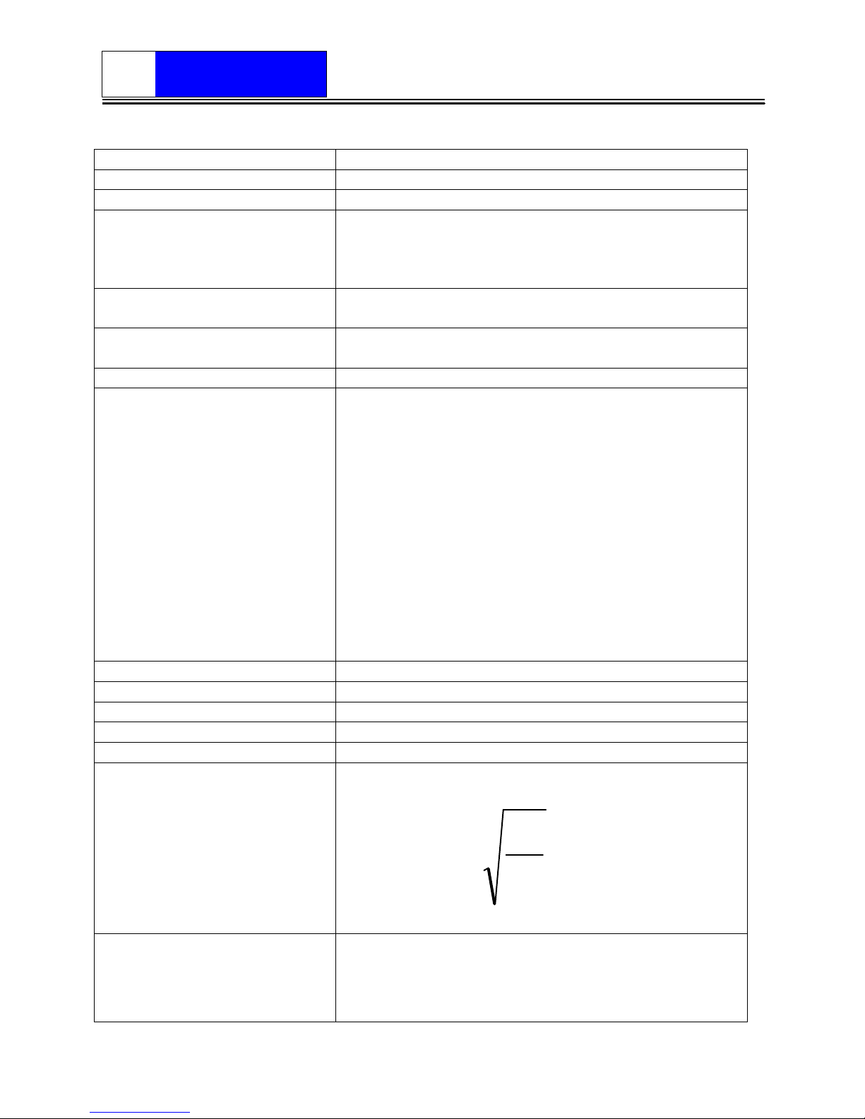
Gamma
Calculated from P
r
– Reflected power and P
f
-
Forward power
f
r
P
P
Gamma =
VSWR
Calculated from Gamma

RFStandard
RF Power Measurement Solutions
Doc# 6001601
Rev1.86
Page 5
Gamma
Gamma
VSWR
−
+
=
1
1
Operating Power
USB power (wall plug or computer) or battery
Connectors
Depends on the max power specification ****
Batteries
Li-Ion
Battery Life
12 Hours minimum
Battery Charge Time
6 hours maximum
Battery Charger
Built in. Power supplied by wall plug adapter or USB
port
isplay
LCD 4 lines of 16 characters
Interfaces
RS-232 standard, USB 2.0
Output ata Rate, Nominal
15 readings/second
Operating Environmental conditions
Humidity, Max.
85% (non condensing)
Operating Temperature
range
+68° to +95°F (20° to 35°C)
Altitude
8.8kPa to 106kPa (6,562 feet (2,000 m) to -1640ft
(-500m)
Case Temperature
(imposed from exterior)
<35°C (95°F)
Storage/Transportation Environmental conditions
Storage Relative Humidity,
Max
95% (non condensing)
Altitude
10,000 feet (3,000 m)
Storage Temperature range
-20° to + 0°C (-4° to +158°F)
* Max Power levels for Forward and Reflected channels and frequency range can
be customized (up to 50kW). The instrument displays the maximum power and
frequency range upon power up.
** Characteristic for narrow band instruments (with max ±5% frequency range)
*** The instrument performs hardware and software averaging for pulse
(modulated) signals. Please read the Averaging and Pulsing Signals Operation
chapter
**** N female for powers up to 1.5kW, HN female for powers up to 5kW, /16EIA and
LC female for powers up to 12kW, 3-1/8EIA flange for powers up to 50kW

RFStandard
RF Power Measurement Solutions
Doc# 6001601
Rev1.86
Page 6
Installation
This chapter provides information about preparing the RF Standard Power Meter
for use.
RF Line Connection
WARNING
Never attempt to connect or disconnect RF equipment from the
transmission line while RF power is ON!
CAUTION
Do not exceed the specified Maximum Power Allowable for the device.
Damage to the Power Meter may occur.
NOTE: FLOATING RF SYSTEMS WARNING: The RF line ground is
connected to the USB and serial communication ground. The meter can be used on
floating RF systems (where the RF ground is at a different potential then the USB or
serial communication ground) only if a proper isolator is used (ex: an optical isolator).
Using the meter without regarding this note can cause permanent damage to the
meter and life hazard.
Observe the arrow on the front panel of the Power Meter. The arrow is indicating
the direction of the RF power.
No damage will occur if the sensor will be connected in reverse direction but the
values for the FWD and REW Power on the LCD display and on the serial
communication will be also reversed.
Connect the end of the Power Sensor labeled “RF IN” to the RF source. Connect
the end labeled “RF OUT” to the load or antenna.
WARNING
DO NOT USE MECHANICALLY OR ELECTRICALLY DAMAGED RF
CONNECTORS. ANY TRACE OF RESIDUE MUST BE CLEANED
BEFORE USING RF CONNECTORS. ENGAGE THE RF
CONNECTORS ALL THE WAY IN. FAILING TO DO SO WILL RESULT
INTO UNCONSISTENT READINGS AND/OR BURNED
CONNECTORS

RFStandard
RF Power Measurement Solutions
Doc# 6001601
Rev1.86
Page
Inspect the RF connectors and cables before use for:
- Burned, bent, pushed in or missing central connector. Do not use such cables!
- Residue on the insulators. Try and clean the insulator using Isopropyl alcohol.
Dry the insulator before use!
Torque the RF connectors to the manufacturer specifications. Failure to do so will
result in unstable readings, damage of the connector and fire hazard.
NOTE: SERIAL COMMUNICATION WARNING: Typical RF systems are
controlled by a CPU thru a serial connection (RS232/Devicenet/Profibus). At the same
time the RF output is at ground connection. If the instrument is connected to the same
CPU a ground loop is created. Depending on the ground leak current this configuration
may or may not work.
The instrument may “freeze” if the ground leak current is too high. As a solution
use either a serial isolator or use a separate CPU (other than the one used to
communicate with the RF generator) to communicate with the instrument. If
necessary, use ON/OFF button to reset the instrument.
AC Line Connection
RF Power Meter is supplied with a universal (90VAC to 264VAC) wall plug
adapter. Let us know if you are going to use the RF Power Meter outside U.S. so we
can supply the proper wall plug.
NOTE: Notify RF Standard if you are going to use the device with non-U.S.
voltages. A proper wall plug adapter will be provided.

RFStandard
RF Power Measurement Solutions
Doc# 6001601
Rev1.86
Page 8
Chapter Two
Operating Instructions
This chapter describes operator controls and indicators on the RF Power Meter.
For remote operation using a USB or RS-232 interface, refer to the instructions in
following two chapters
Front Panel
Charging indicator
Figure 2-1
Load RF Plane Generator RF Plane

RFStandard
RF Power Measurement Solutions
Doc# 6001601
Rev1.86
Page 9
Push Button
esc
ription
Navigational button. Press to increase the
set value or to move UP.
Navigational button. Press to decrease the
set value or to move DOWN.
SET
Press to indicate the value that you want to
set. It will change the cursor position
between line 3 and 4 on display.
If you want to change the frequency, position
the cursor on line 3 (where the frequency is
displayed) then increase/decrease the
frequency value using the arrows.
The frequency will increment/decrement in
x10kHz steps
For additional information displayed (VSWR,
Gamma, Temperature, #Averages), position
the cursor on line 4 and use the arrows to
navigate among options.
ON/OFF
Press to turn the Power Meter On or Off.
Keep the button pressed for at least 1
second for the command to take effect.

RFStandard
RF Power Measurement Solutions
Doc# 6001601
Rev1.86
Page 10
Charging the battery
The charging LED is going to be ON if the Li-Ion battery is charging (from the USB
connection or from the wall plug adapter). The LED will turn OFF when the battery is
fully charged (4.2V)
Battery charge is performed either the instrument is ON or OFF.
Charging time to full capacity depends on how much the battery is discharged
and the power source. Some computer USB ports are limiting the charging current. A
full charge may take up to 6 hours.
Run time on battery is at least 12 hours (typically 16 hours) and decays with the
age of the battery. Standard Li-Ion battery has a life of about 500 charging cycles.
Before a complete discharge (below 3.6V) the instrument will display a message
to recharge and it shuts down automatically to protect the battery. Upon re-power, the
instrument will re-start but if the low battery condition is detected it will shut down.
The instrument has full functionality during re-charging.
NOTE: Battery is not user accessible. User cannot replace the battery!
Table of contents


