Premier 690L Instruction Manual

690L / 690R
SERVICE GUIDELINES
Document # 10008217
THE FIRST NAME IN QUALITY COUPLINGS
WARNING!
• All 294 bolts are considered a serviceable part & cannot surpass 1-year of use. After 1-year of vehicle installation, it is
considered out-of-service and no longer usable.
294 Bolt Service Life Instructions
• The following applies to all Premier Model 690 couplings (690L, 690R, 690T)
• For new 690 coupling or new/replaced 294 bolt: Record the date of installation.
• 6-months after installation date: Remove & inspect entire 294 bolt and look for fractures along entire length of bolt
(preferably using dye penetrant or mag particle testing).
• If 294 bolt looks good: Re-install & continue to use for another 6-months.
• If fractured DO NOT USE: Contact Premier Mfg.
• 1-year after installation date (regardless of service duty): Remove & replace with new 294 bolt.
WARNING: If, at any time, the 690 Coupling is boundup (jackknifed), then the 294 Bolt MUST be replaced immediately! Until
replacement, the 690 Coupling is not to be used. Furthermore, carefully inspect the 690 Coupling; drawbar; drawbar eye; front
end assembly; and tail board for damage.
Note: Prior to disassembly, measure the wear area on the pintle horn. If the wear is at or exceeds 20% of the cross section, the
coupling is to be considered Out of Service. At a minimum, the 692 Hook and 294 Bolt would need to be replaced prior to the
coupling being placed back into service.
spection/Operation/Maintenance
DISASSEMBLY:
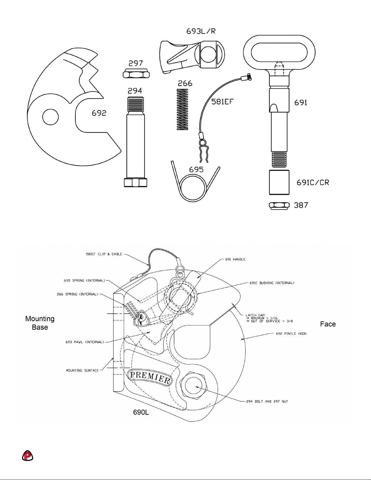
1. Prior to disassembly, familiarize yourself with the location of the various parts in the 690 Coupling. This will assist in the
assembly process.
2. Disassemble coupling, removing all parts from body. Clean and inspect parts and body for wear and/or damage. If wear exists
or damage is noted, replace affected part. NEVER ATTEMPT WELD REPAIR OF ANY DAMAGED OR WORN COMPONENT.
3. Measure the four 690 body holes for wear. The upper (691 Handle) body holes should not exceed 1.300 in diameter. The
lower (294 Bolt) body holes should not exeed 1.156 in diameter. If any measurement is exceeded, the coupling body is to be
considered out-of-service and must be replaced.
ASSEMBLY:
1. All body holes, part holes and pins need to be lubricated with a heavy grease when the parts are reassembled.
2. Lay body of casting on its face, mounting surface up and nose pointing toward you.
Page 1 1-800-255-5387 • www.premier-mfg.comPREMIER MANUFACTURING
Page 2 1-800-255-5387 • www.premier-mfg.comPREMIER MANUFACTURING
3. Place 695 Spring alongside 693 Pawl (one leg nests in groove on side of pawl). With 695 Spring to the right, install the 693
Pawl and spring through the bottom of the body. Make sure that the leg of the 695 Spring nests in groove inside body.
4. Install 691 Handle, locating tapers on pin portion with tapers inside 693 Pawl. Slide 691C Bushing over threaded end of
691 Handle and into body (for 690R the 691CR clip groove must be furthest from body) and secure entire assembly with the
387 Nut.
5. Install 266 Spring. Nest one end of 266 Spring in the recessed pocket of 693L or 693R Pawl, and the other end in the
recessed pocket of the coupling body.
6. While holding the spring in position, rotate 691 Handle clockwise (counter-clockwise for 690R) to the open position and
engage lug 693 Pawl with lug on internal body sidewall (right side). This will hold the handle in the open position. Turn entire
body over and place on mounting base (nose pointing away from you).
7. Position 692 Pintle Hook into body and install 294 Bolt, from right to left, securing the 692 Pintle Hook in position.
8. Align one of the flats on the 294 Bolt head with the rasied stop on the coupling body. Make certain the bolt head is flush with
the coupling body. It’s possible the hole will need to be minorly chamfered, or the bolt stop ground or filed for the 294 Bolt
head to sit completly flush.
9. Remove any grease on the threads of the 294 Bolt prior to installing 297 Locknut. Torque the 297 Locknut to 50 ft-lbs
(Do not exceed 50 ft-lbs of torque).
10. Coupling is now assembled and should be opened and closed several times, testing for smooth and correct operation. Do not
use the coupling if it does not close properly.
11. Lubricate latch assembly where appropriate (DO NOT LUBRICATE PINTLE HOOK WEAR SURFACE ).
WARNING: Do NOT bind-up (jackknife) any application, as stresses can cause damage to the 294 bolt, hitch, drawbar eye, other
components or any combination of them. Jackknifing may result in failure of products or components, resulting in detachment of
the trailer while in use.
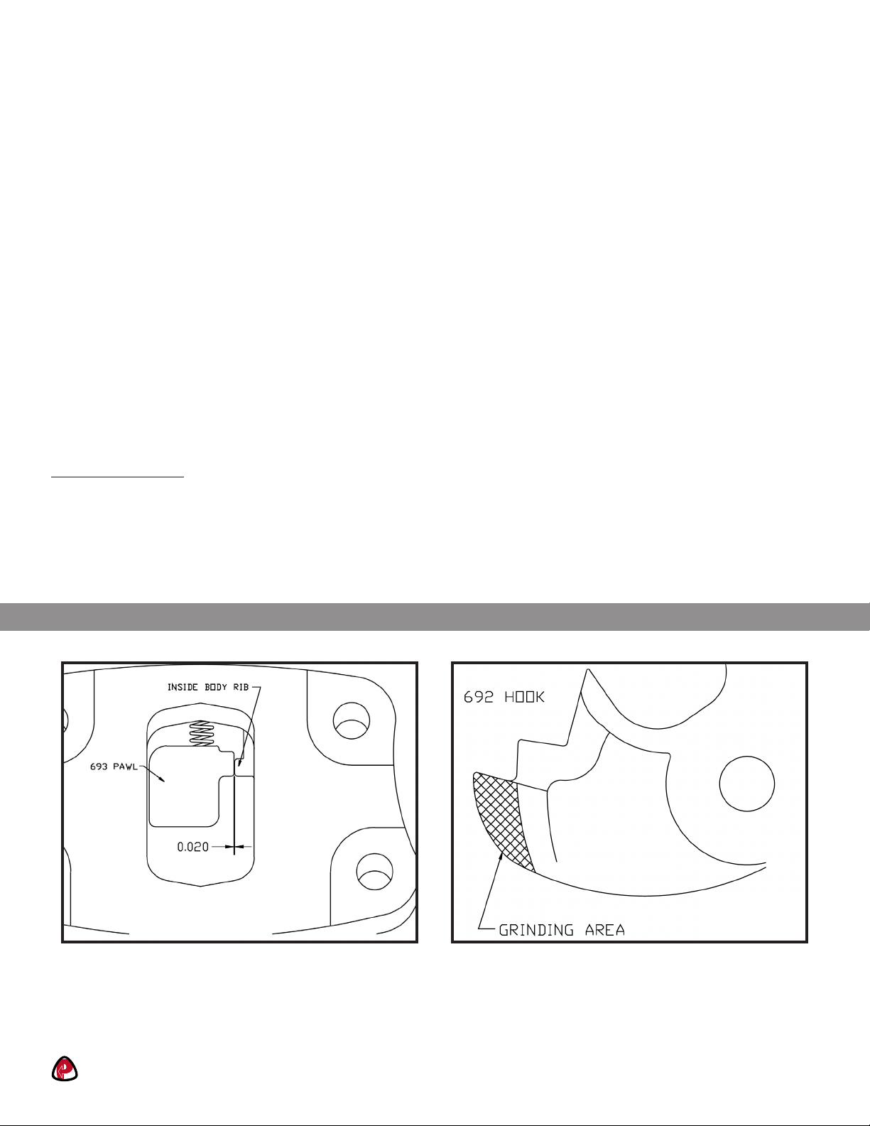
Figure 1 Figure 2
PROPER OPERATION:
• NOTE: The following is for installation of new components.
• When coupling is placed in opened position, there should exist a clearance of at least .020” between the 693 Pawl and the
inside wall of coupling body. (Figure 1)
• When coupling is placed in opened position, the 692 Hook may not fully rotate forward. If this occurs, the 692 Hook may
need light grinding for proper fit and operation. (Figure 2)
Page 3 1-800-255-5387 • www.premier-mfg.comPREMIER MANUFACTURING

Page 4 1-800-255-5387 • www.premier-mfg.comPREMIER MANUFACTURING
ATTENTION!
End Users must read and follow this information.
DISTRIBUTORS & OEM’S: Please ensure that your customers are
made aware of the following information on this page.
1. VERIFY THAT BOTH COUPLING’S AND DRAWBAR EYE’S RATED CAPACITIES MEET YOUR APPLICATION(S)
REQUIREMENTS.
2. DO NOT OVERLOAD COUPLING OR DRAWBAR EYE.
3. INSPECT COUPLING, LATCH AND DRAWBAR EYE FOR CRACKS, BENDING DAMAGE OR EXCESSIVE WEAR.
DO NOT USE IF ANY OF THESE CONDITIONS EXIST!
4. CHECK FOR GAP BETWEEN CLOSED LATCH AND TOP OF HORN OR COUPLING BALL.
DO NOT USE IF GAP IS 3/8 IN. OR MORE.
5. MAKE SURE COUPLING IS LATCHED AND THAT LATCH WILL NOT OPEN.
6. PRIOR TO USE, ALWAYS CONNECT SAFETY CHAINS OF ADEQUATE STRENGTH FOR LOAD(S) BEING TOWED.
7. DO NOT BIND-UP (JACKKNIFE) ANY APPLICATION AS STRESSES CAN CAUSE DAMAGE TO THE COUPLING,
DRAWBAR EYE, OTHER COMPONENTS OR ANY COMBINATION OF THEM. JACKKNIFING MAY RESULT IN
FAILURE OF PRODUCTS OR COMPONENTS, RESULTING IN DETACHMENT OF THE TRAILER WHILE IN USE.
8. DO NOT APPLY LUBRICANTS TO THE COUPLING HOOK OR DRAWBAR EYE LOOP, AS THEY CAN COVER UP
POSSIBLE DAMAGE AND ACCELERATE WEAR.
9. ALWAYS ABIDE BY ALL APPLICABLE STATE AND FEDERAL REGULATIONS GOVERNING SAFE AND PROPER
TRANSPORTATION.
10. NEVER STRIKE ANY OF THESE COMPONENTS WITH A HAMMER OR ANY OTHER DEVICE.
11. ALWAYS VERIFY PROPER OPERATION OF LATCHING SYSTEM AND COUPLING COMPONENTS PRIOR TO DRIVE OFF.
12. NEVER USE A COUPLING THAT YOU DO NOT FULLY UNDERSTAND HOW TO PROPERLY OPERATE AND VERIFY
SECURE LATCHING OF.
13. NEVER REPLACE ANY PART IN ANY OF PREMIER’S ASSEMBLIES WITH NON-PREMIER COMPONENTS. DOING SO
WILL VOID ALL WARRANTY AND POTENTIALLY COMPROMISE THE UNIT’S INTEGRITY, WHICH COULD RESULT IN
PROPERTY DAMAGE, SERIOUS INJURY, OR DEATH.
PREMIER MANUFACTURING
THE FIRST NAME IN QUALITY COUPLINGS
800-255-5387 (503)234-9202
www.premier-mfg.com
WARNING!
Important Installation Instructions:
Do NOT attempt install without first reading all
attached instructions. Installation must be per-
formed by a qualified mechanic only.
Model 690L/690R
Service Guidelines
1-800-255-5387 • www.premier-mfg.comPREMIER MANUFACTURING Page 5
WARRANTY: We warrant all Premier products to be free from defects in material or workmanship for one year. We will
repair or replace, at our option, any Premier product which our examination reveals to be defective, provided that the
product is returned to our factory, at Tualatin, Oregon transportation prepaid, within one year of purchase by the first retail
purchaser. Our warranty does not extend to products which have been subject to misuse, neglect, improper installation,
maintenance or application, nor does our warranty extend to products which have been repaired or altered outside of
3UHPLHU·V facility unless the repair or alteration has been expressly authorized in writing by Premier. This warranty is in
lieu of all other warranties, express or implied, and excludes warranties of merchantability, fitness for a particular purpose and
otherwise, and in no event will Premier be liable for incidental, special, contingent or consequential damages.
DISCLAIMER: Although great care has been taken to ensure accurate information throughout this document, Premier
Manufacturing must reserve the right to alter any information contained within. These changes include but are not limited to:
Dimensional changes, load capacity and availability of any part or assembly.
© 2009 Premier Manufacturing
All rights reserved. Any reproduction of the photographic images or any other portion of this document, including but not
limited to the photocopying, or retention and/or storage in a retrieval system of any kind, is strictly prohibited without prior
express written permission from Premier Manufacturing.
Other manuals for 690L
1
This manual suits for next models
1
Table of contents
Other Premier Industrial Equipment manuals

Premier
Premier 470 Operating manual

Premier
Premier 690L Operating manual

Premier
Premier 270PK Instruction Manual

Premier
Premier 580 COUPLING Operating manual

Premier
Premier 370PK Instruction Manual

Premier
Premier 2200 Instruction Manual

Premier
Premier 2200 Operating manual

Premier
Premier 2200ELL Operating manual

Premier
Premier 240 COUPLING Operating manual

Premier
Premier 330 Operating manual


