
PRAXSYM t-meter User manual

BroadbandWireless
Power Meter
User’s Manual

Warranty concerns or claims should be pursued with the company
from which the product was purchased.
PRAXSYM warrants that all items will be free from defects in material
and workmanship under use as specified in this guide for a period of
one year from date of delivery. PRAXSYM further agrees to repair or
replace, at its discretion, any failure which upon PRAXSYM's inspec-
tion appears to be a result of workmanship or material defect. In no
case, shall PRAXSYM's liability for breach of warranty exceed the pur-
chase price of the items in question. PRAXSYM's liability on any claim
of any kind, for any loss connected with, or resulting from the use of,
performance or breach thereof, installation, inspection, operation or
use of any equipment furnished by PRAXSYM, shall in no case exceed
the purchase price of the goods which give rise to the claim.
Illustrations by Mike Gorman, Prairie Wind Communications, Inc.
Copyright © 2004 Castle Rock Microwave, LLC
T-METER
Page i

Page ii
PRAXSYM
Table of Contents
Introduction to the t-meter
1
Using the t-meter
2
Measuring Transmitter Power 5
Measuring Transmission Line Loss 7
Measuring VSWR of Antenna and Terminations 9
Specifications
11
Appendix — VSWR Table 13
Appendix—Notes 15

T-METER
Page 1
Introduction to the t-meter
The t-meter is a handheld broadband power meter capable of detect-
ing forward and reflected power in a microwave radio system. The
meter is capable of detecting various types of wireless broadband
modulation schemes in the license exempt 2.4, 5.3, and 5.8GHz fre-
quency bands, with application specific coverage at 4.9GHz (PM-
4900), 900MHz (PM-900) and 3.5GHz (PM-3500). Coverage at 5.4-
5.7GHz is also common to the PM-4900, PM-900 and PM-3500.
The meter was designed with the system integrator and installer in
mind. It is the perfect tool for the verification of transmitter power,
transmission line loss characteristics, and antenna performance.
Key features of the t-meter:
-affordability
-portability
-use in multiple microwave bands
-verification of system installation

Using the t-meter
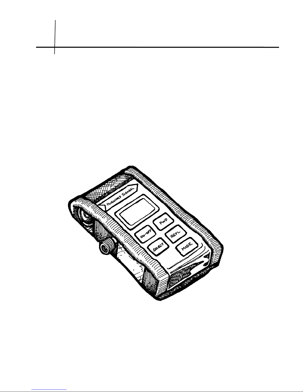
The t-meter ships with a durable nylon case that is secured with hook
and loop flaps. The package is designed such that the meter can be
used while still in the nylon case. The flaps that cover and protect the
meter can be secured behind the unit while it is in use. This is shown
on the front cover of this manual.
Packaged with the meter is a male-to-male type “N” adapter (in the left
pocket), a 50Ωtermination (right pocket), and a 2W 10dB attenuator
(in the pocket above the meter).
Most transmitters have a female type “N” connector on them. The
double male adapter can be used to connect the meter directly to the
transmitter. The meter should always have a 50Ωload on its output
when connected to a transmitter. Depending on the type of test, this
can be an antenna or the 50Ωtermination included in the kit. The
20dB attenuator is included for use when the device under test trans-
mits a signal higher than 20dBm in amplitude. When using the 10dB
attenuator it is a good idea to change the offset to “+10” in the MODE
settings (page 4). Note that the input to the 2W 10dB attenuator
should not exceed 33dBm (2W). If an attenuator with a higher power
rating is used, the input into the attenuator can be increased such
that the output of the attenuator does not exceed 20dBm. The at-
tenuator offset should be set for “+00” when no attenuator is used.
50Ωtermination
2W 10dB attenuator
Male-to-male adapter
Page 2
PRAXSYM

The meter should always be inserted into the system in the forward
power direction. Use the arrow labeled “FORWARD SIGNAL” as a
guide when connecting the meter.
Pressing and quickly releasing the ON-OFF button turns the meter
on. The meter will display “Below Range” if it is not connected to a
source that is within it’s dynamic range (0 to 20dBm).
Once the meter is connected to a source, and a 50Ωtermination is
placed on it’s output, the forward and reflected power can be meas-
ured. If the meter is not properly terminated the forward power
measurement may be inaccurate.
If the signal applied to the meter exceeds 20dBm, the meter will read
“Exceed Range”.
VSWR is automatically calculated and displayed according to the for-
ward and reflected measurements. The accuracy of the VSWR meas-
urement depends on several variables (forward and reflected power
levels, attenuation in the transmission line, etc).
Button Description
ON-OFF: Turns the unit ON or OFF. Unit also powers down five
minutes after last key depression. Powers up to the last
state that it was in.
SELECT: Used with MODE key to make selections.
MODE: First push - Displays remaining battery life.
Second push - Allows selection of the unit of power
(dBm or mW) on the display.
Third push - Allows selection of the frequency band of
interest (scrolls through available bands).
Fourth push - Allows selection of the inline attenuator
offset (0dB, 10dB, 20dB, or30dB).
Fifth push - Exits MODE and returns to selected moni-
toring state (FWD or REFL.)
Depressing FWD or REFL also exits MODE at any time.
FWD: Displays forward power and VSWR. A right-pointing
arrow in the upper right of the display indicates the
meter is measuring forward power. The power
T-METER
Page 3
measurement is displayed continuously. The VSWR is
displayed for two seconds on the bottom display line
and then is replaced for one second by the band indi-
cator (“2.4G” for example) and the in-line attenu-
ator setting (“+00,” “+10,” “+20”, or “+30”).
REFL: Similar in function to the FWD button, except it dis-
plays the reflected power and shows a left-pointing
arrow in the upper right of the display.
Page 4
PRAXSYM

Measuring Transmitter Power
The meter should be connected to the transmitter according to the
“FORWARD SIGNAL” label on the meter (see the illustration on the
opposite page). Depending on the gender of the type “N” connector
on the transmitter it may be necessary to use the double male type
“N” adapter. The meter should be terminated with the 50Ωload in-
cluded in the kit.
Turn the t-meter on by pressing the ON-OFF button. Select the fre-
quency band of interest by pressing the MODE button until the fre-
quency list is shown. Use the SELECT button to scroll through, and
select the appropriate band. A small arrow should be displayed be-
side the band (2.4 for example).
Press the FWD button to read the forward power. A small right-
pointing arrow will appear in the upper right side of the display. This
is the amplitude of the signal (in dBm or mW, depending on the unit
selected in the MODE menu) in the forward direction.
The meter is designed to detect signals between 0 and 20dBm in the
forward direction, and –20 to 17dBm in the reflected. Damage can
occur to the meter if the forward power into the meter (without the
attenuator) exceeds 36dBm.
Most broadband radio transmitters deliver less than 100mW
(20dBm). The 2W 10dB attenuator can be used for sources that are
between 20 and 30dBm in amplitude. Remember to apply the appro-
priate offset in the MODE setting (+10 if the attenuator included in
the kit is used). If the output of the transmitter exceeds 33dBm
(2W), an attenuator of the appropriate power rating and insertion
loss should be used to lower the signal to a level below 20dBm. Us-
ing the MODE button an offset can be configured for attenuators up
to 30dB. If an attenuator is not used, the offset should be set to
“+00”.
While the forward power is displayed constantly on the top line of
the display, the bottom line alternates between the VSWR and the
frequency band and offset settings.
NOTE: A good way to verify proper operation of the 50Ωtermination
(included in the kit) is to make sure that a VSWR of 1.2:1 is displayed
when the meter is connected according to the diagram on the oppo-
site page. If the VSWR is not 1.2:1 the termination should be re-
placed.
T-METER
Page 5

Page 6
PRAXSYM

Measuring Transmission Line Loss
Measure the forward power of the transmitter as shown on the previ-
ous pages. Use the 50Ωtermination included in the kit as the load.
Make note of the forward power reading.
Disconnect the meter from the transmitter. NOTE: The transmitter
should always be powered down when there is no load present, or
when connecting the meter or transmission line. Connect the trans-
mission line directly to the transmitter with the proper amount of
attenuation (if necessary).
Move the t-meter to the opposite end of the transmission line. Con-
nect the meter as shown on the opposite page. Take another for-
ward power reading. Subtract this forward power reading from that
taken directly off the back of the transmitter. This is the amount of
signal lost due to attenuation in the transmission line and termina-
tions.
This value can be compared to the loss specifications of the transmis-
sion line and connectors to verify that the coax is properly termi-
nated.
T-METER
Page 7
Other manuals for t-meter
1
Table of contents
Other PRAXSYM Measuring Instrument manuals


