
PKP DS11 User manual

Instruction Manual
DS11
Plastic variable area flowmeter with
glass measuring tube
PKP Prozessmesstechnik GmbH
Borsigstraße 24
D-65205 Wiesbaden- ordenstadt
Tel.: ++49-(0)6122-7055-0
Fax: ++49-(0)6122-7055-50
Email: info@pkp.de www.pkp.de

Table of Contents
Safety Information..................................................................................................................2
Functional Description...........................................................................................................3
Mounting and Adjustment......................................................................................................3
Limit Switches........................................................................................................................4
Maintenance and Care.........................................................................................................11
Safety Information
General Instructions
To ensure safe operation, the device should only be operated according to the specifica -
tions in the instruction manual. The requisite Health & Safety regulations for a given
application must also be observed. This statement also applies to the use of accessories.
Every person who is commissioned with the initiation or operation of this device must have
read and understood the operating instructions and in particular the safety instructions!
The liability of the manufacturer expires in the event of damage due to improper use, non-
observance of this operating manual, use of insufficiently qualified personnel and unau-
thorized modification of the device.
Proper Usage
The flowmeters of the DS11 series are used to monitor the continuous flow of liquids and
gases. Any other use of the instrument is prohibited and outside the scope of application.
Unless otherwise stated, the scales of the devices refer to air at 1.2 bar abs. At 20 °C or
water.
In particular, applications in which shock loads occur (for example, pulsed operation)
should be discussed and checked in advance with our technical staff.
The series DS11 flow meter devices should not be deployed as the sole agents to prevent
dangerous conditions occurring in plant or machinery. Machinery and plant need to be
designed in such a manner that faulty conditions and malfunctions do not arise that could
pose a safety risk for operators.
Dangerous substances
For dangerous media such as e.g. Oxygen, Acetylene, flammable or toxic substances as
well as refrigeration systems, compressors, etc. must comply with the relevant regulations
beyond the general rules.
DS11 Instruction manual 11/2021 page 2

ualified Personnel
The DS11 devices may only be installed by trained, qualified personnel who are able to
mount the devices correctly. Qualified personnel are persons, who are familiar with
assembling, installation, placing in service and operating these devices and who are suit-
ably trained and qualified.
Inward Monitoring
Please check directly after delivery the device for any transport damages and deficiencies.
Additional with reference to the accompanying delivery note the number of parts must be
checked.
Claims for replacement or goods which relate to transport damage can only be considered
valid if the delivery company is notified without delay.
Functional Description
The variable area flow meter must be installed vertically. The flow direction is from low to
high scale.
The connection is made with connection pieces corresponding to the instrument version.
The lines must be routed centrically to the connection holes of the measuring instrument
with as little stress as possible. If necessary, the pipes must be supported in order to avoid
the transmission of vibrations to the measuring instrument.
Mounting and Adjustment
The actual operating pressure and the temperature of the medium in the installation must
not exceed the maximum values specified in the specifications.
1. Close the needle valve on the flowmeter.
2. Open the shut-off valve upstream and downstream of the flowmeter.
3. For liquids, ensure careful venting of the pipeline.
In the Case of gases, allow the operating pressure to rise slowly.
Avoid bouncing (danger of glass breakage).
4. Open the needle valve and set the desired flow rate.
5. The flow value is read off at the upper edge of the float.
If the operating parameters deviate from the calibration data (flow range, medium, pres-
sure, density and temperature), the displayed flow value can be converted in accordance
with VDI / VDE guideline 3513.
DS11 Instruction manual 11/2021 page 3

Limit Switches
The flowmeters can be equipped with a maximum of two limit switches.
The switching function of the limit switch can be designed as monostable or bistable.
Monostable function: Switching pulse as float passes through switching point,
independent of direction of movement.
Bistable function: Stable changeover as float passes through switching point.
Example (bistable): Above limit: switching point "High"
Below limit: switching point "Low"
For switching performance and electrical data refer to section "Technical data".
Electrical connections:
Connection of limit switch - 2-wire AMUR (standard):
1 Lower limit switch to terminal 1
2 Upper limit switch to terminal 2
The connection box includes an EMC filter unit.
DS11 Instruction manual 11/2021 page 4

Connection of limit switch - 2-wire AMUR, without connection box:
1 Limit switch (without connection box)
2 Blue cable -
3 Brown cable +
4 External EMC filter
5 Receiver device
When connecting to an EMC filter, the ground terminal must be connected to the back rail
of the flowmeter.
Connection of limit switch - 3-wire (transistor):
bn - brown: supply voltage +
bk - black: switch
bu - blue: supply voltage -
DS11 Instruction manual 11/2021 page 5

Settings of limit switches:
1 Clamping screw
2 Back rail
3 Limit switch
The following procedures are to be performed:
•Remove both clamping screws 1.
•Slide the limit switch over the measuring glass.
•Use the two clamping screws 1 to fasten the limit switch 3 to the back rail 2 of the
measuring device.
•Re-install the protective cover following installation.
For installation after the fact, the measuring glass must be removed. Refer to chapter
"Maintenance and care”
CAUTIO !
When setting the limit switch, be careful to lay the cable so that it does not get damaged.
Avoid canting of the limit switch during installation: glass breakage
The connecting lead of the limit switch is guided through a hole in the base of the device
and
sealed.
Observe the following for bistable limit switches with external EMC filters in separate DI
rail
housing:
The EMC filter unit and the back rail of the meter must be galvanically connected and
grounded.
An isolation switching amplifier with intrinsically safe circuit controls is necessary to
operate the
AMUR limit switches.
DS11 Instruction manual 11/2021 page 6
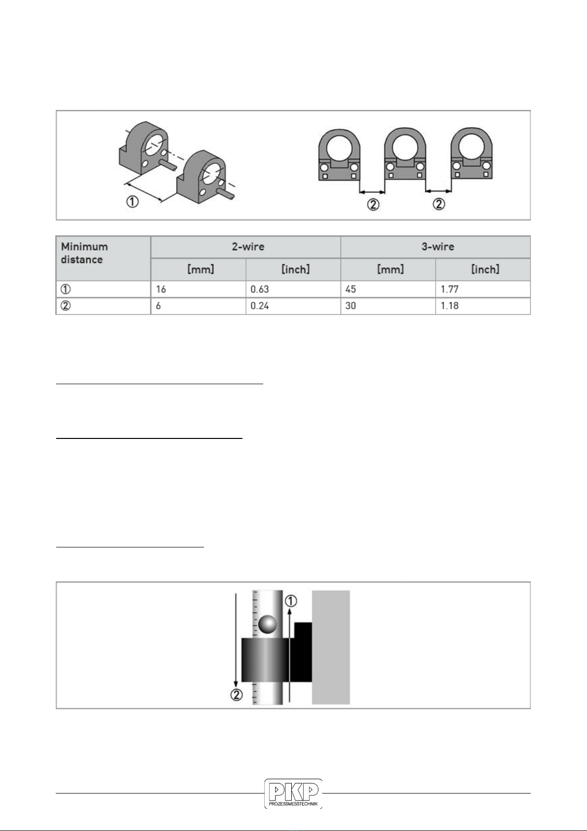
Minimum distance between two limit switches:
Where two limit switches are used in one device and also where meters with limit switches
are in close proximity of each other, minimum distances must be maintained in order to
avoid mutual influence of the switches.
Switching performance of limit switches
2-wire limit switch AMUR, monostable
Float outside of the limit switch: signal ≥3 mA
Float inside of the limit switch (centre): signal ≤1 mA
2-wire limit switch AMUR, bistable
Independent of the float position and passage 1: signal ≥3 mA
Prerequisite: the float is outside the limit switch.
I FORMATIO !
For the proper initialisation after power up, the bistable AMUR limit switch should pass
through each of 1 and 2 once.
3-wire limit switch, transistor
Independent of the float position and passage 2: signal ≤1 V
Prerequisite: the float is outside the limit switch.
Switching performance
DS11 Instruction manual 11/2021 page 7

Reversed function of limit switch:
The bistable limit switches can be changed from normally open switch to normally closed
switch.
The pre-fabricated connection cable must be long enough to do this.
When installing and setting, make sure the cable is not damaged when laid.
•Loosen terminal screw 1.
•Turn turnbuckle 2 counter-clockwise to loosen.
•Pull out the measuring glass along with the limit switch.
•Turn limit switch 180°.
•Install the measuring glass.
•Tighten turnbuckle 2 by hand.
•Use a 3 mm pin to tighten the turnbuckle by turning 4 to max. 5 times in 120°
increments 3 in a clockwise direction.
CAUTIO !
To avoid breakage, the measuring glass must be positioned centrically between the
gaskets.
Test the leak tightness by suitable measures prior to start-up.
DS11 Instruction manual 11/2021 page 8

Grounding connection:
The measuring unit is grounded on the back rail 1 (M4 thread). This connection only
ensures electrostatic grounding of the device and does not meet the requirements for
equipotential bonding.
Position of the ground terminal
DA GER!
The grounding wire may not transfer any interference voltage.
Do not use this grounding cable to ground any other electrical devices.
Ingress protection:
The limit switches with connection housing meet all requirements of ingress protection
IP65.
Therefore it is essential to observe the following points:
•Use only original gaskets. They must be clean and free of any damage. Defective
gaskets must be replaced.
•The electrical cables used must be undamaged and must comply with regulations.
•The cables must be laid with a loop 3 upstream of the measuring device to prevent
water from getting into the housing.
•The cable feedthroughs 2 must be tightened.
•Close the unused cable feedthroughs with blanking plugs 1
DS11 Instruction manual 11/2021 page 9

Ingress protection
DA GER!
After all servicing and maintenance work on the measuring device, the specified protection
class
must be ensured again.
Technical data of limit switches:
1) For devices with the valve at the top in the output and devices with flow regulators for
variable outlet pressure, the function is inverted!
I FORMATIO !
The limit switches with ring diameters of 15 mm / 0.6" as max. contact can only be used
up to 60 l/h / 15.8 GPH water or 2400 l/h / 89.3 SCFH air (outer diameter of the measuring
glass).
DS11 Instruction manual 11/2021 page 10
Table of contents
Other PKP Measuring Instrument manuals


