PAW K35 Owner's manual

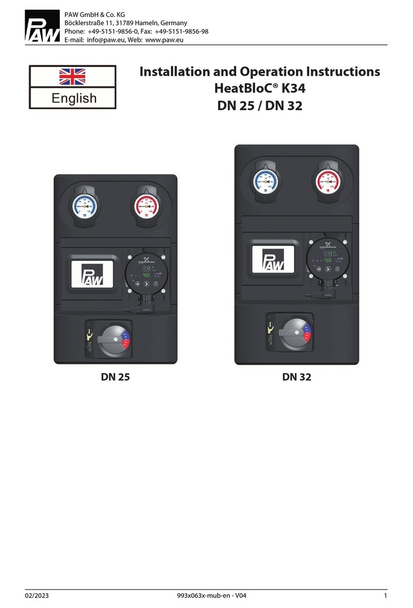
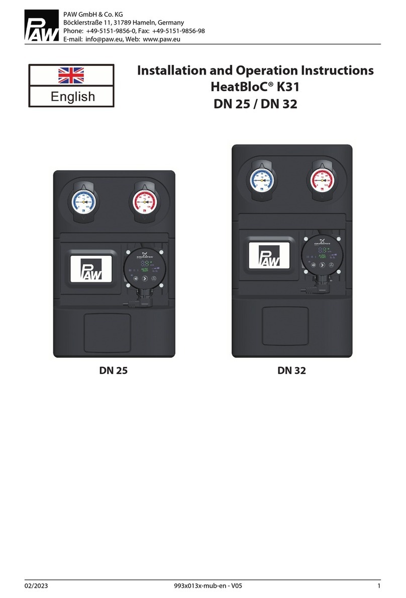
Installation and Operation Instructions
HeatBloC® K35 - DN 25
with 3-temperature mixing valve
PAW GmbH & Co. KG
Böcklerstraße 11, 31789 Hameln, Germany
Phone: +49-5151-9856-0, Fax: +49-5151-9856-98
02/2023 9936093x-mub-en - V04 1

Table of Contents
1 General Information...................................................................................................3
1.1 Scope of these instructions........................................................................................3
1.2 Designated use........................................................................................................... 3
2 Safety instructions......................................................................................................4
3 Product description.................................................................................................... 5
3.1 Equipment...................................................................................................................5
3.2 Function.......................................................................................................................6
3.2.1 3-temperature mixing valve [specialist]...................................................................6
3.2.2 Change of the flow line [specialist]........................................................................... 7
3.2.3 Check valve and non-return valve [specialist]......................................................... 10
3.3 Accessories: Actuator (optional)............................................................................... 12
4 Mounting and installation [specialist]].....................................................................13
4.1 Accessories: Cutting-ring compression fitting (not included in the scope of
delivery).......................................................................................................................14
4.2 Mounting of the HeatBloC®........................................................................................15
5 Scope of delivery [specialist]..................................................................................... 17
6 Technical data............................................................................................................. 19
6.1 Pressure drop and pump characteristic curves........................................................20
7 Disposal....................................................................................................................... 21
8 Notes............................................................................................................................22
Table of Contents
02/2023 9936093x-mub-en - V04 2

1 General Information
Carefully read these instructions before installation and commissioning. Save these
instructions in the vicinity of the installation for future reference.
1.1 Scope of these instructions
These instructions describe the installation, commissioning, functioning and the operation of a mixed
HeatBloC®.
For other components of the installation, such as the pump, the controller or the modular distribution
manifold, please observe the instructions of the corresponding manufacturer. The chapters called
[specialist] are intended for specialists only.
1.2 Designated use
The product may only be used in heating circuits taking into consideration the technical limit values
indicated in these instructions.
It must not be used in drinking water applications.
Improper usage excludes any liability claims.
This product complies with the relevant directives and is therefore labelled with the CE mark. The
Declaration of Conformity is available upon request, please contact the manufacturer.
Only use PAW accessories with the product.
1 General Information
02/2023 9936093x-mub-en - V04 3

2 Safety instructions
The installation and commissioning as well as the connection of electrical components require
technical knowledge commensurate with a recognised vocational qualification as a fitter for
plumbing, heating and air conditioning technology, or a profession requiring a comparable level of
knowledge [specialist].
The following must be observed during installation and commissioning:
●relevant local and national regulations
●accident prevention regulations of the professional association
●instructions and safety instructions mentioned in these instructions
CAUTION
Personal injury and damage to property!
The product must only be used in heating circuits filled with heating water according
to VDI 2035 / Ö-Norm H 5195-1.
►The product must not be used in drinking water applications.
WARNING
Material damage due to mineral oils!
Mineral oil products cause lasting damage to seals made of EPDM, whereby the sealant properties
are lost. We do not assume liability nor provide warranty for damage to property resulting from
sealants damaged in this way.
►It is imperative to prevent the EPDM sealing elements from making contact with substances
containing mineral oils.
►Use a silicone- or polyalkylene-based lubricant free of mineral oil such as Unisilikon L250L
and Syntheso Glep 1 from Klüber or a silicone spray.
2 Safety instructions
4 9936093x-mub-en - V04 02/2023

3 Product description
The HeatBloC® K35 is a preassembled group of fittings for heating circuits. The HeatBloC® is mounted
directly onto a mounting plate or onto a distribution manifold. The distance between the pipe axis of
the HeatBloC® and the wall must be at least 10 cm, as the connection C-3 is on the back side of the
mixing valve.
Attention: To use the PAW piping sets (item no. 36092KS2 / KS3 / KS4), the centre distance, that is the
distance to the wall, must be at least 150 mm!
3.1 Equipment
Rear view of mixing valve with flow on the
right
A-1 Flow to the consumer circuit
A-2 All-metal thermometer with immersion sleeve,
integrated in the ball valve (flow)
B Heating pump
C 3-temperature mixing valve
C-1 High-temperature flow from the buffer tank
C-2 Return to the buffer tank
C-3 Additional connection for the supply of the
low-temperature flow on the back side of the
mixing valve
C-4 Non-return valve, can be opened
D Return pipe
D-1 Check valve, can be opened
E Design insulation with optimised function
F-1 Return from the consumer circuit
F-2 All-metal thermometer with immersion sleeve,
integrated in the ball valve (return)
3 Product description
02/2023 9936093x-mub-en - V04 5

3.2 Function
K35 - 3-temperature mixing valve with additional
connection for a second flow temperature
The 3-temperature mixing valve is used in combination
with a buffer tank which can be heated either by a solar
installation, a solid fuel boiler or a conventional boiler.
If the consumer only needs a low temperature level, such
as for radiant panel heating systems, the 3-temperature
mixing valve first takes the flow water from the
intermediate part of the storage tank. Only when the
temperature in this part is no longer sufficient, the hot
water from the upper part of the tank is used.
Application range:
●Heating systems with buffer
tank & solar heating support
●Control of radiant floor
heating & panel heating
systems
By using two parts of the storage tank for two different
flow temperatures, the energy from the buffer tank can be
used more efficiently.
The return temperatures are low and the stratification in
the buffer tank is maintained.
3.2.1 3-temperature mixing valve [specialist]
The 3-temperature mixing valve, driven by an electric actuator, adjusts the flow temperature of the
consumer circuit to the required value by means of the flow sensor and the controller. It is equipped
with a second flow connection (C-3) on the back side. This connection allows to withdraw water with a
lower flow temperature from the intermediate part of the tank, f. ex. of a buffer tank.
K35: A check valve is integrated in this second flow connection to avoid unwanted circulation in the
mixing valve. This check valve is designed for heating pumps with a maximum head of 7 m. If you
want to use a more powerful pump, an additional check valve may be necessary in the feed line.
MC45: A non-return valve (D-1) prevents unwanted circulation.
3 Product description
6 9936093x-mub-en - V04 02/2023

Rear view of mixing valve with flow on the right
Expl. K35: Front view of mixing valve with flow on the
right
Position 0-5:
The flow temperature is reached by mixing
return water and water from the
intermediate part of the tank.
Position 5:
100% supply from the intermediate part of
the tank
Position 5-10:
The flow temperature is reached by mixing
water from the intermediate part and the
upper part of the tank.
3.2.2 Change of the flow line [specialist]
Dismounting of the mixing valve
1. Take off the thermometer handles (A-2, F-2) and remove the insulating front shell.
2. Take the group of fittings out of the insulating back shell.
3. Dismount the mixing valve (C).
3 Product description
02/2023 9936093x-mub-en - V04 7

Retrofitting of the mixing valve
1. Loosen the screw (1).
2. Take off the rotary knob (2) from the cock rod.
3. Loosen the screws (3).
4. Remove the cover plate (4).
5. Loosen the two screws (5).
6. Remove the front plate (6).
7. Extract the sealing bush (7) with the cock plug (8) from the housing of the mixing valve.
8. Loosen the screws (10) on the back side of the mixing valve and take off the cover (9).
9. Pull the sealing plug (11) to the front by using pliers. Remove the flow-reducing plate (12) by
pushing from front to back.
10. Turn the housing of the mixing valve by 180°.
11. Mount the flow-reducing plate (12) on the back side and the sealing plug (11) on the front side.
3 Product description
8 9936093x-mub-en - V04 02/2023
12. Mount the cover (9) on the back side of the mixing valve. The letters on the cover indicate the
correct assembly position:
flow on the left: L points upwards flow on the right: R points upwards
Assembly position for mixing valve with flow on
the left
Assembly position for mixing valve with
flow on the right
13. Fix the cover (9) by using the screws (10).
14. Insert the sealing bush (7) with the cock plug (8) into the channel of the mixing valve.
15. Screw down the front plate (6) using the screws (5).
Mixing valve with flow on the right Mixing valve with flow on the left
16. Turn the cover plate (4) in such a way that the marking PAW is at the bottom and that the scale
is positioned as shown in the figure above.
17. Fix the cover plate (4) by using the screws (3).
18. Put the rotary knob (2) onto the cock rod.
19. Fix the rotary knob (2) on the cock plug (8) by using the screw (1).
3 Product description
02/2023 9936093x-mub-en - V04 9

Retrofitting and commissioning of the heating circuit
1. Interchange the return pipe (D) and the flow pipe with the pump (B).
Consider the flow direction of the pump!
Turn the pump head such that the terminal box is directed to the top or to the centre of the
group of fittings.
2. Dismount and interchange the ball valves.
3. Mount the HeatBloC® and connect it to the installation.
4. Check all union nuts before commissioning and firmly tighten them if necessary.
5. Mount the insulation only after having carried out a pressure test. Mount the thermometer
handles (A-2, F-2) in a final step.
3.2.3 Check valve and non-return valve [specialist]
The HeatBloC® is equipped with a check valve (D-1, opening pressure 200 mm wc) in the return pipe
and with a non-return valve (C-4, opening pressure 50 mm wc) in the return of the mixing valve. The
valves can be opened. An additional check valve is integrated in the connection C-3 (low-temperature
flow).
This check valve cannot be opened!
3 Product description
10 9936093x-mub-en - V04 02/2023
Other manuals for K35
1
Table of contents
Other PAW Industrial Equipment manuals

PAW
PAW HeatBloC K31 Owner's manual

PAW
PAW HeatBloC K31 - DN 20 Owner's manual

PAW
PAW HeatBloC K34R Owner's manual

PAW
PAW HeatBloC K31 Owner's manual

PAW
PAW HeatBloC K33 - DN 20 Owner's manual

PAW
PAW SolarBloC midi 2S Installation and operation manual

PAW
PAW SolarBloC midi 2D Installation and operation manual

PAW
PAW HeatBloC K38 Owner's manual

PAW
PAW HeatBloC K32 Owner's manual

PAW
PAW HeatBloC K32 Owner's manual