Omega FPR310 Series User manual
e-mail: info
@
omega.com
For latest product manuals:
www.omegamanual.info
User’s Guide
Shop online at
omega.com
SM
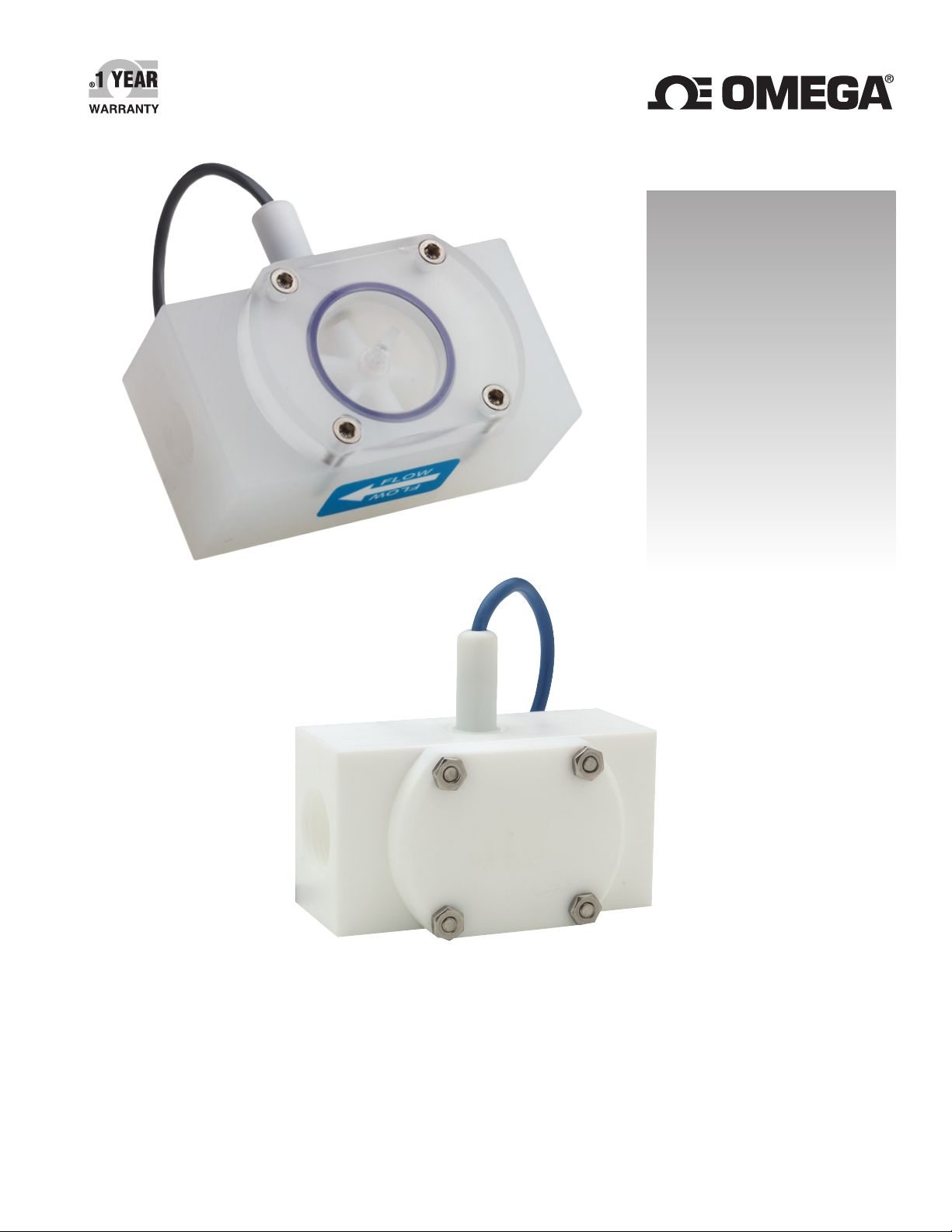
FPR300
FPR310
FPR300/310 SERIES
Low-Flow Meter

Servicing North America:
U.S.A. Omega Engineering, Inc.
Headquarters: Toll-Free: 1-800-826-6342 (USA & Canada only)
Customer Service: 1-800-622-2378 (USA & Canada only)
Engineering Service: 1-800-872-9436 (USA & Canada only)
Tel: (203) 359-1660 Fax: (203) 359-7700
For Other Locations Visit omega.com/worldwide
omega.com [email protected]
The information contained in this document is believed to be correct, but OMEGA accepts no liability for any errors it contains, and reserves
the right to alter specifications without notice.

General Information
General Information ...................................................................................................................................................Page 4
Features ..........................................................................................................................................................................Page 4
Specications ................................................................................................................................................................Page 5
Dimensions ....................................................................................................................................................................Page 5
Flow Range.....................................................................................................................................................................Page 5
Pressure Drop Curve...................................................................................................................................................Page 5
Installation & Connections
Piping Requirements..................................................................................................................................................Page 6
K-Factor ...........................................................................................................................................................................Page 6
Connections to Control Devices ............................................................................................................................Page 6
Repair
Rotor Replacement .....................................................................................................................................................Page 7
Sensor Replacement...................................................................................................................................................Page 7
FPR300/310 Parts List ................................................................................................................................................Page 8
Troubleshooting
Problem ...........................................................................................................................................................................Page 9
Probably Causes...........................................................................................................................................................Page 9
Things to Try..................................................................................................................................................................Page 9
TABLE OF CONTENTS FPR300/310 SERIES INSTRUCTIONS
Page 3 omega.com
GENERAL INFORMATION
These versatile impeller owmeters are available in 3/8”,
1/2”, 3/4”, and 1” nominal pipe sizes with female NPT
threads. They employ jewel bearings to allow for very low
minimum ow rates and superior life.
The FPR300, with a body of polypropylene, is an economical
choice for metering water or low corrosion uids. The lens
cover is available in a choice of materials: acrylic for visual
ow indication of low-corrosion uids; polypropylene
when more corrosion resistance is needed. The standard
rotor assembly is PVDF with tungsten carbide shaft. The
O-ring is EPDM.
The FPR310 offers greater chemical resistance with a PTFE
body and cover, PTFE-coated FKM O-ring, and standard
PVDF/ceramic rotor assembly.
The pulse output of these meters is compatible with many
different types of controls, including a full range of Omega
rate displays and controls. The Omega DPF-143 and
DPF-144 provide ow rate and total ow indication. The
DPF-144 also includes 4-20 mA output capability. The FMG-
1000-MAW may be used for blind 4-20 mA transmission.
Features
FPR300/310 SERIES INSTRUCTIONS
Page 4 omega.com
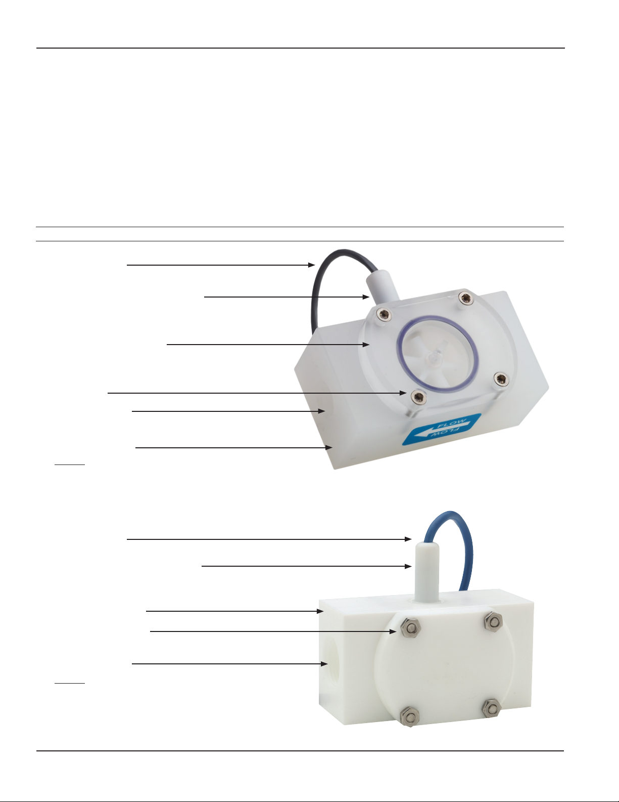
FPR300
Thread-in Sensor, Field Replaceable,
6–24 Vdc Pulse
18’ Sensor Cable
Standard Acrylic Top with Clear
Removable Lens Assembly
(optional polypropylene top
without clear lens)
Polyproylene Body
Female NPT Ports
Hex Screws
Internal
• Jewel Bearings—Ruby Ring and Ball
• PVDF/Tungsten Carbide Rotor Assembly (PVDF/Ceramic or
PVDF/Silicon Carbide optional)
• EPDM O-Ring (FKM or PTFE-coated FKM optional)
Thread-in Sensor, Field Replaceable,
6–24 Vdc Pulse
18’ Sensor Cable
PTFE Body and Top
Female NPT Ports
Screws with Hex Nuts
Internal
• Jewel Bearings—Ruby Ring and Ball
• PVDF/Ceramic Rotor Assembly (PVDF/Silicon Carbide
optional)
• PTFE-coated FKM O-Ring (FKM or EPDM optional)
FPR310
GENERAL INFORMATION
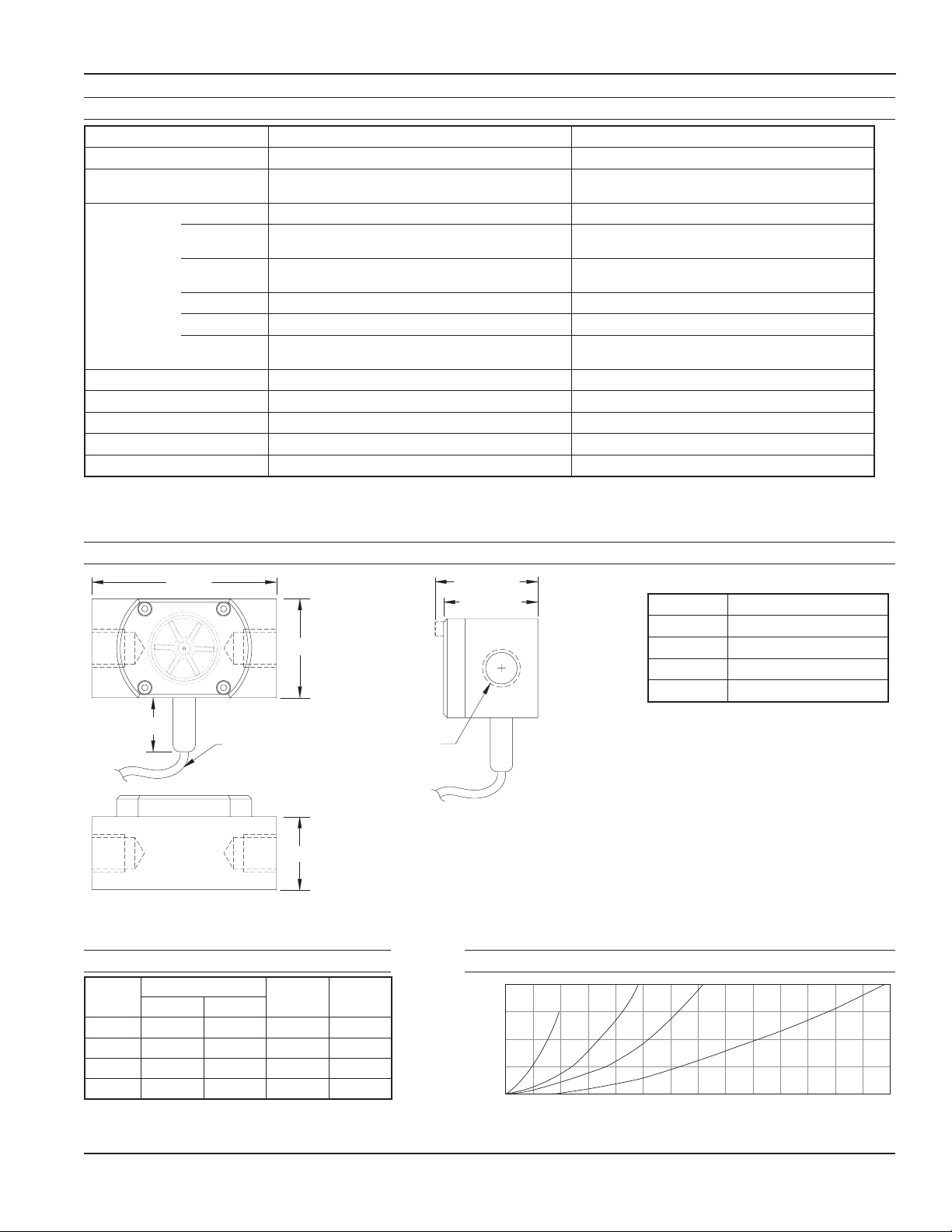
4.10
2.20
2.10 (FPR300)
2.25 (FPR310)*
18 Ft. Cable
(standard)
Female NPT
thread size varies
with model #.
See chart
1.20
*NOTE:
FPR310 cover
screws are not
recessed
1.625
Dimensions
Specications*
FPR300 FPR310
Connection Ports 3/8”, 1/2”, 3/4”, 1” —Female NPT thread 3/8”, 1/2”, 3/4”, 1” —Female NPT thread
Sensor Cable 18 ft (6 m) standard—maximum cable run 2000 ft
(607 m)
18 ft (6 m) standard—maximum cable run 2000 ft
(607 m)
Materials Body Polypropylene PTFE
Rotor PVDF—2 magnet
(6 magnet high resolution optional)
PVDF—2 magnet
(6 magnet high resolution optional)
Shaft Nickel tungsten carbide
(ceramic or silicon carbide optional)
Zirconia ceramic
(silicon carbide optional)
O-Ring EDPM (FKM or PTFE-coated FKM optional) PTFE-coated FKM (FKM or EDPM optional)
Bearings Ruby ring and ball Ruby ring and ball
Cover Acrylic with clear lens
(polypropylene without clear lens optional)
PTFE
Maximum Temperature 160˚ F (70˚ C) 180˚ F (82˚ C)
Maximum Pressure 150 psi (10 bar) 150 psi (10 bar)
Accuracy ±1% of full scale ±1% of full scale
Power 6–36 Vdc, 2 mA min. 6–36 Vdc, 2 mA min.
Outputs Current sinking pulse, 6–24 Vdc Current sinking pulse, 6–24 Vdc
* Specications subject to change. Please consult our website for current data (omega.com)
Model # NPT Thread Size
-038 3/8”
-050 1/2”
-075 3/4”
-100 1”
Pressure Drop (PSI)
Flow (GPM)
0510 15 20 25 30 35
5
10
15
20
3/8" 1/2" 3/4" 1"
Model # K-Factor* (pulses/gal) Gal/Min Liter/Min
FPR310 FPR300
-038 1394 1417 0.07–5 0.27–18.9
-050 634 658 0.1–10 0.38–37.9
-075 476 468 0.2–20 0.75–75
-100 250 254 0.5–40 1.9–150
*Nominal K-factors (based on averages) for standard 2-magnet FPR310
and FPR300. High resolution (6-magnet) K-factors are approximately
tripled.
Flow Range Pressure Drop Curves
FPR300/310 SERIES INSTRUCTIONS
Page 5 omega.com

INSTALLATION
Piping Requirements
Standard ttings are female NPT. If the piping connected
to the meter is metallic, care should be taken not to
overtighten. Straight pipe of at least ve diameters
upstream of the meter is recommended. Vertical or
horizontal installations are acceptable.
K-Factor
The meter is factory calibrated. The K-factor is found on
the label on the meter body and must be input into the
control/display for accurate reading.
WARNING:
This meter has low-friction bearings. Do
not at any time test operation of the meter
with compressed air. Doing so will subject
it to rotational speeds many times those
for which it was designed, and will certainly
damage the rotor, shaft, and/or bearings.
K-factor on label
INSTALLATION & CONNECTIONS
CONNECTIONS
Connecting to Control Devices
It is often desirable to connect an FPR300/310 ow sensor
to a PLC or industrial computer board, and the sensors are
well suited for this. Typically it can be connected directly,
or with a single resistor added. The pickup sensors are
current sinking (NPN) GMR devices that require 6–36 Volts
DC and 2 mA current. They can connect directly to a PLC
or computer board if:
1. The sensor power supply on the PLC is 6–36 Vdc (24
Vdc is typical).
2. The sensor power supply can provide at least 2 mA
(100 mA is typical).
3. The sensor input on the PLC can accept a current
sinking device.
4. The PLC frequency response > ow meter output
frequency.
Input designed for current sinking devices (NPN)
If the PLC input only accepts current sourcing devices, a
pull-up resistor must be added. Typically, on a 24 Vdc input
a 2.2 K Ohm resistor will be effective.
Input designed for current sourcing (PNP) devices
Since the three-wire pickup sensors are solid state, they
do not exhibit switch bounce and can be used at relatively
high frequencies.
If the PLC is equipped with a 4-20 mA analog input module,
it is necessary to order the FPR300/310 Series ow sensor
with some form of 4-20 mA transmitter. Two options are
the FMG-1000-MAW blind transmitter and the DPF144
indicating transmitter. Follow the connection diagrams for
these products to connect to the analog input.
Red
White
Black
Red
White
Black
Signal
+DC Voltage
Ground
Signal
+DC Voltage
Ground
Figure 1 Figure 2
Input Designed for Current
Sinking (NPN) Devices
Input Designed for Current
Sourcing (PNP) Devices
2.2K Ohm Pull-up
Resistor
NPN
Device
NPN
Device
NPN Device NPN Device
Red
White
Black
Red
White
Black
Signal
+DC Voltage
Ground
Signal
+DC Voltage
Ground
Figure 1 Figure 2
Input Designed for Current
Sinking (NPN) Devices
Input Designed for Current
Sourcing (PNP) Devices
2.2K Ohm Pull-up
Resistor
NPN
Device
NPN
Device
NPN Device PNP Device
FPR300/310 SERIES INSTRUCTIONS
Page 6 omega.com
REPAIR
Rotor Replacement
There is only one moving part to this meter. The bearings
are made of ruby, which rarely wears out or needs
replacement unless they have been physically damaged by
severe shock. The shaft is integrally molded into the rotor,
and shaft and rotor are replaced as one part. (You may wish
to replace the bearings, using the bearing removal tool,
while the meter is disassembled for rotor replacement). To
replace the rotor, disconnect the meter and remove the
four screws that hold the cover in place. Lift the cover and
remove the rotor (see parts diagram below).
When putting in the new rotor, be sure that the ends of
the shaft are in both bearings before tightening the cover.
The rotor can be easily dropped into the bottom bearing.
Starting the shaft into the upper bearing requires a bit of
care. It is easier if the rotor is spinning, which can be done
by lightly blowing into a port. When the upper bearing
plate drops into place, hold it down and check for free
spinning (by blowing lightly) before replacing the cover.
Check that the O-ring is in its seat on the bearing plate
before replacing the cover. Replace the cover, insert the
four cap screws and tighten.
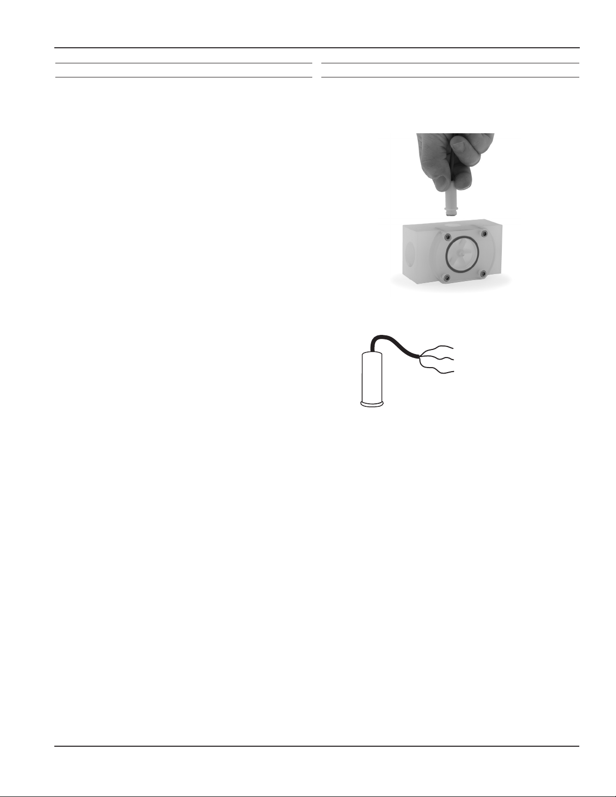
Sensor Replacement
The sensor ordinarily does not need replacement unless it is
electrically damaged. If replacement is necessary, unscrew
the sensor by hand. Screw the replacement sensor in and
tighten by hand.
Reconnect the sensor according to the diagram below.
(BLACK) Power (-)
(WHITE) Signal
(RED) Power (+) 6-24 Vdc
SES SENSOR CONNECTION
FPR300/310 SERIES INSTRUCTIONS
Page 7 omega.com
REPAIR
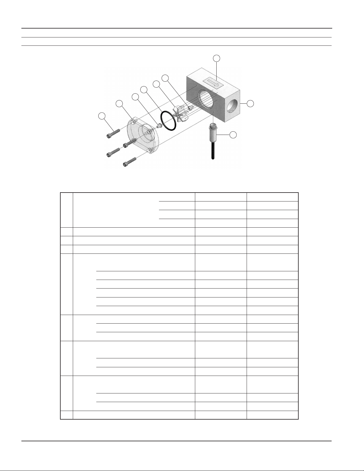
FPR300/310 Parts List
2
1
8
3
4
5
3
6
7
FPR300 FPR310
1 Body -038 100221 100269
-050 100222 100268
-075 100223 100267
-100 100224 100266
2 Flow direction Label 100256 100256
3 Bearing Assembly (includes 2) 103313 103313
Bearing Removal Tool (not shown) 100372 100372
4 Rotor with Shaft
PVDF/Ceramic (2 magnet) 103930 103930
PVDF/Carbide (2 magnet) 103931 n/a
PVDF/Silicon Carbide (2 magnet) 103933 103933
PVDF/Ceramic (6 magnet, high res) 100453 100453
PVDF/Carbide (6 magnet, high res) 103932 n/a
PVDF/Silicon Carbide (6 magnet, high res) 103934 103934
5 O- Ring EPDM 100264 (standard) 100264 (optional)
FKM 100219 (optional) 100219 (optional)
PTFE-coated FKM 100973 (optional) 100973 (standard)
6 Cover (after 5/2005)
Polypro 100849 Not available
Acrylic 100848 Not available
PTFE Not available 100847
7 Cover Screws (4 required)
Hexscrew 100310 Not applicable
Screw (requires hex nut 100025) Not applicable 100022
Hex nut (requires screw 100022) Not applicable 100025
8 Sensor 100419 100419
FPR300/310 SERIES INSTRUCTIONS
Page 8 omega.com

TROUBLESHOOTING FPR300/310 SERIES INSTRUCTIONS
Page 9 omega.com
Problem Probable Cause Things to Try...
No signal after installation Insufcient ow Consult Flow Rate Chart
Reduce pipe size or use different sensor
Bad connections to control
electronics
Check connections at control:
Red (+), Black (-), White (signal)
Incompatible control Use 6–36 Vdc power supply
Add pull up resistor, if using current-sourcing
device
Damaged or missing rotor Remove ow sensor from tting and check for free
spinning; replace rotor
Failed magnetic sensor Replace magnetic sensor
Inaccurate metering Not enough straight pipe
between meter and severe ow
disturbance
Move meter away from ow disturbance or eld
calibrate
Wrong K-Factory entered Check tting for K-Factor, check indicator to see if
it is entered properly ("Set K" on DPF143/144)
Magnetic sensor failing to pick up
each blade
Remove ow sensor from pipe. If indicator is
DPF143/144, set K to 1.00, turn rotor slowly by
hand, indicator should count each blade; replace
sensor
Wrong time units on ow
indicator
If using DPF143/144, check left side of display (sec,
min, hr, day); change to desired unit

FPR300/310 SERIES INSTRUCTIONS
Page 10 omega.com
This manual suits for next models
1
Table of contents
Other Omega Measuring Instrument manuals

Omega
Omega DPG1000B User manual

Omega
Omega FDT-25W User manual

Omega
Omega HHP400 User manual

Omega
Omega FTB8000B User manual

Omega
Omega HHP680 User manual

Omega
Omega TCL-3M165E2 Series User manual

Omega
Omega SP-005 User manual

Omega
Omega DPG1000DAR-30V100 User manual

Omega
Omega PHCN-962 User manual

Omega
Omega HFH81 User manual

Omega
Omega FTB-4000 Series User manual

Omega
Omega DPG1001AD User manual

Omega
Omega HHM598 User manual

Omega
Omega DP18 series User manual

Omega
Omega MASS FLOW FMA-1900 User manual

Omega
Omega SP-013 User manual

Omega
Omega FMA1700A User manual

Omega
Omega HX71 Series User manual

Omega
Omega DFG-RS5 User manual

Omega
Omega M-4292/1006 User manual


