OfiTE 120-75 User manual

Atmospheric Consistometer
#120-75 (115V)
#120-75-1 (220V)
Instruction Manual
Updated 3/6/2023
Ver. 8
OFI Testing Equipment, Inc.
11302 Steeplecrest Dr. · Houston, Texas · 77065 · U.S.A.
Tele: 832.320.7300 · Fax: 713.880.9886 · www.ote.com
©Copyright OFITE 2015

OFITE, 11302 Steeplecrest Dr., Houston, TX 77065 USA / Tel: 832-320-7300 / Fax: 713-880-9886 / www.ote.com 1
Intro..................................................................................................2
Description......................................................................................2
Features...........................................................................................2
Requirements .................................................................................2
Components ...................................................................................3
Setup................................................................................................5
Loading the Test Cells ...................................................................6
On-Screen Display .........................................................................7
Operation.........................................................................................8
Calibration.......................................................................................9
Torque Head ...............................................................................9
Temperature..............................................................................10
Motor Speed .............................................................................10
Timer.........................................................................................10
Test Setup ..................................................................................... 11
Maintenance..................................................................................13
Warranty and Return Policy ........................................................15
Table of
Contents

OFITE, 11302 Steeplecrest Dr., Houston, TX 77065 USA / Tel: 832-320-7300 / Fax: 713-880-9886 / www.ote.com 2
The Model 60 Atmospheric Consistometer is designed to condition cement
slurries as specied within API Specication 10. Determination of rheological
properties and examination of free water content require that the cement
slurry be conditioned prior to testing. The OFITE Model 60 was specically
developed to perform these duties.
A cement slurry is prepared according to the procedure outlined in the
API Specication 10 and then placed in the slurry containers of the
Model 60 Atmospheric Consistometer. The slurry is stirred at 150 RPM
by an API-designed paddle assembly. The temperature is controlled by
a microprocessor, which displays the process temperature via a digital
indicator. Consistency, measured in Bearden Units of Consistency, is
determined by measuring the deection of a calibrated spring. The spring is
connected to a pointer that rotates on a scale (numbered 1 through 10) on
the slurry container lid. This deection is created by the amount of torque that
the cement slurry exerts on the paddle, which is a function of the consistency
of the cement. The API denes 100 Bc as 2,080 g-cm of torque and each
number on the lid is a multiple of 10 (1 equals 10 Bc, 5 equals 50 Bc, and 10
equals 100 Bc).
- Redesigned frame and bearings reduces noise during operation
- Dual countdown timers that provide audible and visual notication for
each container
- Program and control temperature with multiple proles on the touch-
screen display
- Process temperature displayed on the touch screen
- Cooling coil for low temperature conditioning (optional chiller available)
- Maximum operating temperature of 200°F
- Unit is operated at atmospheric pressure
- Heat transfer uid is continuously circulated
- Heater wattage is 1,500
- Slurry container rotational speed is 150 RPM
- Dual container design
- Stainless steel temperature bath
- Deadweight calibration unit
- Size: 14.5" × 15.5" × 24.5" (37 × 39 × 62 cm)
- Weight: 95 lb (43.1 kg)
- Crated Size: 32" × 21" × 32" (81 × 53 × 81 cm)
- Crated Weight: 200 lb (90.7 kg)
- Water Supply for Cooling
- Water Drain
- 220 Volt, 50/60 Hz, 2.2 KVA Power Source
- 120 Volt, 50/60 Hz, 4.4 KVA Power Source
Intro
Description
Features
Requirements

OFITE, 11302 Steeplecrest Dr., Houston, TX 77065 USA / Tel: 832-320-7300 / Fax: 713-880-9886 / www.ote.com 3
Components #120-001 Mineral Oil, 1 Gallon, Qty: 3
#120-75-8 Motor Timing Pulley
#120-75-9 Weight Hanger
#120-75-10 Slotted Weight Set
#120-75-16 Calibration Stand
#120-75-17 Drive Housing
#120-75-18 Potentiometer Assembly
#120-75-19 Paddle Assembly
#120-80-6 Motor
#120-511 Slurry Cup Shear Pin
#121-001 Container O-rings
#121-002 Retaining Ring
#121-007-3 Main Bearing
#121-008 Thermocouple
#121-009 Timing Belt
#121-013 Slurry Container
#121-014 Container Bottom
#172-24 Solid State Relay
#174-14 Motor Controller
For 115 VAC Only:
#120-75-2 Water Solenoid Valve
#121-010 Heater
#122-074-1 Fuse, 5 Amp, 5 mm × 20 mm
#122-078 Fuse, 15 Amp, 5 mm × 20 mm
#152-37-3 AC Power Cord
For 230 VAC Only:
#120-75-3 Water Solenoid Valve
#121-010-1 Heater
#122-073-1 Fuse, 3 Amp, 5 mm × 20 mm
#122-075 Fuse, 7 Amp, 5 mm × 20 mm
#220-15A-EURO AC Power Cord

OFITE, 11302 Steeplecrest Dr., Houston, TX 77065 USA / Tel: 832-320-7300 / Fax: 713-880-9886 / www.ote.com 4
Optional:
#120-76 Spare Parts for #120-75:
#120-001 Mineral Oil, 1 Gallon, Qty: 3
#120-75-19 Paddle Assembly, Qty: 2
#120-511 Slurry Cup Shear Pin, Qty: 10
#121-001 Container O-rings, Qty: 8
#121-002 Retaining Ring, Qty: 2
#120-004 Calibration Spring, Qty: 2
#121-005 Cap Nut
#121-008 Thermocouple
#121-009 Timing Belt, Qty: 2
#121-010 Heater
#121-013 Slurry Container
#121-014 Container Bottom, Qty: 2
#122-074-1 Fuse, 5 Amp, 5 mm × 20 mm, Qty 6
#122-078 Fuse, 15 Amp, 5 mm × 20 mm, Qty: 3
#120-76-1 Spare Parts for #120-75-1:
#120-001 Mineral Oil, 1 Gallon, Qty: 3
#120-75-19 Paddle Assembly, Qty: 2
#120-511 Slurry Cup Shear Pin, Qty: 10
#121-001 Container O-rings, Qty: 8
#121-002 Retaining Ring, Qty: 2
#120-004 Calibration Spring, Qty: 2
#121-005 Cap Nut
#121-008 Thermocouple
#121-009 Timing Belt, Qty: 2
#121-010-1 Heater
#121-013 Slurry Container
#121-014 Container Bottom, Qty: 2
#122-073-1 Fuse, 3 Amp, 5 mm × 20 mm, Qty: 6
#122-077 Fuse, 10 Amp, 5 mm × 20 mm, Qty: 3
#152-55 Bath/Circulator, Refrigerated and Heated, 115 VAC, 60 Hz
#152-55-1 Bath/Circulator, Refrigerated and Heated, 230 VAC, 50 Hz

OFITE, 11302 Steeplecrest Dr., Houston, TX 77065 USA / Tel: 832-320-7300 / Fax: 713-880-9886 / www.ote.com 5
Setup
Potentiometer
Speed Control
Tank Drain
Coolant Drain
Coolant Supply
1. Carefully remove the unit from the crate and place it close to a water
supply and drain.
Coolant Supply and Coolant Drain lines are ¼" tube connections and the
Coolant Supply port should be connected to a 40 PSI (275.8 kPa) water
source. The Coolant Drain is the port located on the right of the lower
back instrument panel.
2. Fill the bath with approximately 2 gallons of mineral oil to submerge the
test cells at least half way. The oil must cover the thermocouple inside the
bath.
Do not overll the bath.
3. Connect the unit to a grounded and fused 10-amp electrical supply.
4. The rotational speed of the unit may need to be adjusted periodically.
a. Turn on the electrical power and start the motor.
b. Measure the rotational speed of the rotators with a hand held
tachometer. The rotational speed should be 150 rpm ± 15.
c. If adjustment is required, loosen the three screws on the back panel
of the unit and open the door. Directly to the right of the motor is the
motor speed potentiometer.
d. To increase the rotational speed, turn the potentiometer speed control
clockwise. Turn it counterclockwise to reduce the speed.

OFITE, 11302 Steeplecrest Dr., Houston, TX 77065 USA / Tel: 832-320-7300 / Fax: 713-880-9886 / www.ote.com 6
Loading the
Test Cells
1. Prepare the cement slurry and pour it into the slurry container as specied
in API Specication 10.
2. Insert the paddle into the test cell. Make sure the point on the end of the
paddle is inserted into the hole in the bottom of the test cell.
3. Place the lid on the test cell by sliding the torque shaft over the end of the
paddle. Turn the lid clockwise until the pin in the torque shaft engages
with the slot in the paddle shaft.
4. Continue turning the lid to lock it in place on top of the test cell.
5. Lower the test cell into the bath and lock it in place with the locking pins.
Torque Shaft
Locking Pin Locking Pin
Locking Pin

OFITE, 11302 Steeplecrest Dr., Houston, TX 77065 USA / Tel: 832-320-7300 / Fax: 713-880-9886 / www.ote.com 7
The on-screen display controls the temperature, motor, and timer for the At-
mospheric Consistometer. At the bottom of the screen is a series of buttons.
The Real-Time Data button returns you to the main screen, which shows the
Bath Temperature, Temperature Setpoint, and the two timers.
The Test Setup button takes you to the Test Setup screen where you can
create advanced temperature proles. See page 11 for more information.
The Calibrate button takes you to the Calibration screen where you can cali-
brate the various instruments in the Consistometer. See page 9 for more
information.
The Utilities button takes you to the Utilities screen where you can set the
temperature units (°F or °C).
The Start Motor button starts the motor. Press the Stop Motor button to stop
the motor.
The Start Cooling button opens the cooling valve and allows cooling water
to circulate through the bath. Press Stop Cooling to close the valve and stop
the ow of water.
The Start Heating button turns on the heater. Press the Stop Heating button
to turn the heater o.
On-Screen
Display

OFITE, 11302 Steeplecrest Dr., Houston, TX 77065 USA / Tel: 832-320-7300 / Fax: 713-880-9886 / www.ote.com 8
Operation The OFITE Atmospheric Consistometer performs two functions. It can be
used to condition a cement slurry or to perform a thickening time test as
detailed in API Specication 10.
1. Turn the “Power” switch on.
2. On the display, touch the temperature setpoint and enter the test
temperature or use the up and down arrows to set the test temperature.
3. Load one or both test cells. Refer to “Setup - Loading the Test Cells” on
page 6 for details.
It is very important that you begin the test within one minute of
mixing the cement slurry.
4. Touch the “Start Motor” button to start the motor.
5. Touch the “Start Heating” button to start the heater.
6. On the “Test Timer 1” or “Test Timer 2” touch the hours, minutes, or
seconds and enter the appropriate value to set the timer. When the timer
counts down to zero, an alarm will sound.
7. Touch the “Start” button to start the timer.
8. When the test or conditioning is complete, touch the “Stop Motor”, “Stop
Heating”, and “Start Cooling” buttons.
9. When the slurry containers are cool enough to handle, remove them from
the unit and pour the cement slurry into the container for the intended
test. Thoroughly clean the containers with soap and water. Be sure to
remove any residual cement.
OFITE, 11302 Steeplecrest Dr., Houston, TX 77065 USA / Tel: 832-320-7300 / Fax: 713-880-9886 / www.ote.com 9
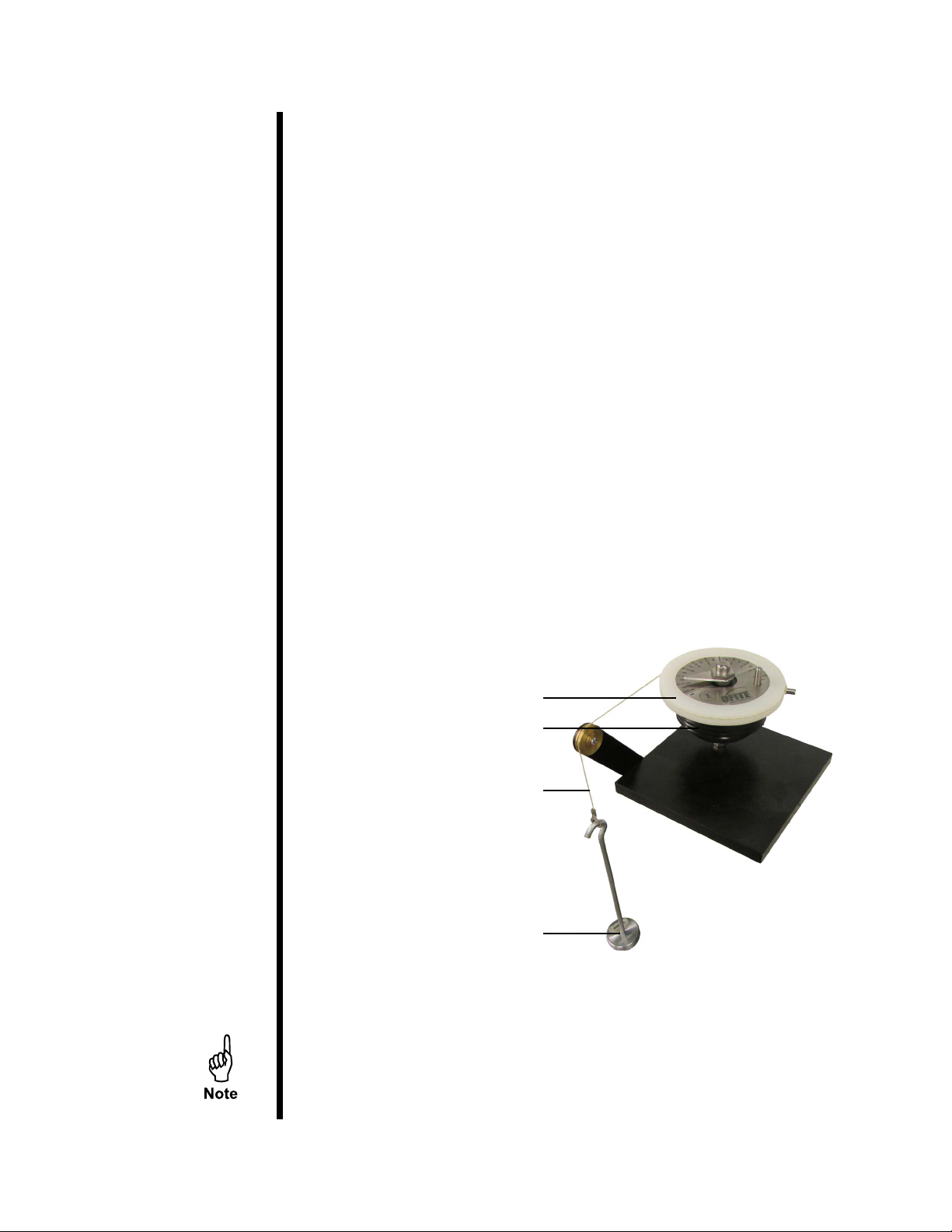
Calibration
Torque Head
Calibrating the torque head provides a reference point for interpreting test
results. The calibration kit provided uses dead weight to simulate resistance
on the torque head. To calibrate, three dierent weights are applied and
the corresponding torque head readings are recorded. During operation,
compare the torque head reading to those recorded during calibration to
determine the amount of resistance being put on the torque head.
Before calibrating the torque head, test the container paddle for excessive
friction by running the sample container without any cement slurry in it. If
the paddle is bent and rubbing on the side of the slurry container or if the
bearings are damaged, excessive friction will show on the dial (refer to the
maintenance section on page 13 for more information). Correct any defects
before calibrating the torque head.
Calibration instructions are described in API-RP-10-B. Your instrument is
equipped with an instrument-mounted calibration unit.
1. Place the torque head onto the calibration stand.
2. Place the calibration ring around the torque head.
3. Wrap the deadweight calibration cord counterclockwise around the
calibration ring and over the roller.
4. Place 400 g on the weight hanger and attach it to the calibration cord.
Calibration Ring
Torque Head
Calibration Cord
Hanger and Weight
When adding weights, remember that the hook weighs 50 grams.
Therefore, to test the potentiometer at 200 g, you only need to add
150 g to the hook.
This manual suits for next models
1
Table of contents
Other OfiTE Measuring Instrument manuals


