Nitto TGF450 Series User manual

User’s Manual Rev1.0
Date:15/07/2015 User’s Manual
1/47
TGF450 Series
Thermal Mass Flowmeter
User’s Manual
Nitto Instruments Co.,Ltd Japan
Hefei Comate Intelligent Sensor Technology Co,. Ltd

User’s Manual Rev1.0
Date:15/07/2015 User’s Manual
2/47
Dear Customer:
Thanks for choosing our flowmeter products. Please read this manual carefully to know how to
install and use this product to ensure its best performance. If you should encounter a problem when
using the product, please do not hesitate to let us know. We are going to take no responsibility if the
flowmeter is damaged because of anyone repair or replace any parts of it with our permission.
Support
Please reach to us according to the contact information below to get support or update of our VFM60
vortex flowmeter:
zWebsite
http://www.comatemeter.com
zTelphone:
+86-0551-63653542
zE-mail:
supports@ comatemeter.com
Place an order
If you need to place an order or need to know the status of your processing orders, please contact us
according to below information:
Phone: +86-0551-63653542
Website: www.comatemeter.com
Email: sales@comatemter.com
Address:2nd floor, Building D2, Hefei Innovation Industrial Park,No.800 Wangjiang West Road,Hefei
Tech Development Zone, Hefei, China
Postal code:230088

User’s Manual Rev1.0
Date:15/07/2015 User’s Manual
3/47
TABLEOFCONTENTS
SUPPORT.........................................................................................................................................2
PLACEANORDER............................................................................................................................2
1GENERAL......................................................................................................................................6
1.1MODELNUMBERANDGENERALSPECIFICATION.........................................................................6
1.2PACKINGLIST.............................................................................................................................6
1.3STORAGE...................................................................................................................................6
1.4MEASURINGPRINCIPLE..............................................................................................................6
2INSTALL........................................................................................................................................7
2.1FINDMOSTSUITABLELOCATION................................................................................................7
2.2REQUIREMENTONSTRAIGHTPIPELINE.....................................................................................8
2.3REQUIREMENTONINSERTIONDIRECTION.................................................................................9
2.4PROCEDUREOFINSTALLATION.................................................................................................10
9)INSERTTHEMETERTOTHEDEPTHSASCALCULATEDWITHTHEHOTTAPMOUNTINGTOOL.
(PLEASEREFERENCETOTHEMANUALOFHOTTAPMOUNTINGFORDETAILS).NOWHOLDTHE
SLEEVE(PARTNO.3)WITHAWRENCHANDTIGHENTHENUT(PARTNO.4)WITHANOTHERWRENCH.
MAKESURETHENUTSLEEVEISHOLDINGTHEMETERTIGHTENLY..................................................13
3WIRING......................................................................................................................................13
3.1WIRINGFORTERMINALBOARD...............................................................................................14
3.2SHELLGROUNDINGANDELIMINATIONOFINTERFERENCE........................................................15
3.4REQUIREMENTONWIRING......................................................................................................15
4DISPLAY......................................................................................................................................16
4.1INTRUCTIONOFMULTI‐FUNCTIONALLCDDISPLAY...................................................................16
4.2UNITOFTHEVARIABLEDISPLAYED...........................................................................................17
4.3THREEBUTTONSETTING..........................................................................................................18
4.4TOTALFLOWDISPLAYING.........................................................................................................18
4.5STATUS....................................................................................................................................19
5SETTING.....................................................................................................................................19
5.1HOWTOSET............................................................................................................................19
5.1.1CODESETTING......................................................................................................................19
5.1.2DIGITALSETTING...................................................................................................................20

User’s Manual Rev1.0
Date:15/07/2015 User’s Manual
4/47
5.2SETTINGLIST............................................................................................................................22
CHART5.1CODESETTINGADDRESS...............................................................................................22
CHART5.2DIGITSSETTINGADDRESS..............................................................................................25
5.3EXAMPLEOFSETTING..............................................................................................................26
5.4PASSWORDSETTINGINSTRUCTION..........................................................................................26
6INSTRUCTIONOFRS485MODBUSCOMMUNICATION.................................................................27
6.1INTERFACEREGULATION..........................................................................................................27
6.2COMMENDS............................................................................................................................29
6.3CALCULATIONOFCRCPARITYCODE.........................................................................................31
6.4THEFLOATDATEFORMATOFTHEINSTRUMENT.......................................................................31
6.5THESEQUENCEOFTHEFLOATDATEBYTESOFINSTRUMENT.....................................................32
6.6MODBUSERRORREPONSE.......................................................................................................32
6.7EXAMPLESOFCOMMUNICATION.............................................................................................33
7INTRODUCTIONOFHARTCOMMUNICATIONPROTOCOL.............................................................33
7.1HARTCOMMANDS...................................................................................................................33
7.1.1COMMAND0:READTRANSMITTERUNIQUEIDENTIFIER........................................................34
7.1.2COMMAND1:READPRIMARYVARIABLEVALUE(PV).............................................................34
7.1.3COMMAND2:READPRIMARYVARIABLE’SCURRENTANDPERCENTAGEVALUE......................34
7.1.4COMMAND3:READPRIMARYVARIABLECURRENTANDDYNAMICVARIABLES......................35
7.1.5COMMAND6:WRITEPOLLINGADDRESS...............................................................................35
7.1.6COMMAND11:READUNIQUEIDENTIFIERASSOCIATEDWITHTAG.........................................36
7.1.7COMMAND12:READMESSAGE.............................................................................................36
7.1.8COMMAND13:READTAG,DESCRIPTOR,DATE......................................................................36
7.1.9COMMAND14:READPRIMARYVARIABLESENSORINFORMATION:DEVICESERIALNUMBER
ANDLIMITS...................................................................................................................................37
7.1.10COMMAND15:READPRIMARYVARIABLEOUTPUTINFORMATION......................................37
7.1.11COMMAND16:READFINALASSEMBLYNUMBER.................................................................37
7.1.12COMMAND17:WRITEMESSAGE.........................................................................................38
7.1.13COMMAND18:WRITETAG,DESCRIPTOR,DATE...................................................................38
7.1.14COMMAND19:WRITEFINALASSEMBLYNUMBER...............................................................38
7.1.15COMMAND34:WRITEPRIMARYVARIABLEDAMPINGVALUE..............................................39

User’s Manual Rev1.0
Date:15/07/2015 User’s Manual
5/47
7.1.16COMMAND35:WRITEPRIMARYVARIABLERANGEVALUES.................................................39
7.1.17COMMAND36:WRITEPRIMARYVARIABLEUPPERLIMITVALUE..........................................39
7.1.18COMMAND37:WRITEPRIMARYVARIABLELOWERLIMITVALUE.........................................40
7.1.19COMMAND40:ENTER/EXITPRIMARYVARIABLECURRENTMODE.......................................40
7.1.20COMMAND45:TRIMPRIMARYVARIABLECURRENTDACZERO............................................40
7.1.21COMMAND46:TRIMPRIMARYVARIABLECURRENTDACGAIN............................................41
8MAINTAINING.............................................................................................................................41
8.1HOWTOCHANGETHETRANSMITTER’SDIRECTION..................................................................41
8.2REPLACEATRANSMITTERCIRCUITBOARDS.............................................................................42
8.3REMOVETHEFLOWMETER......................................................................................................42
8.4HOWTOCLEANTHESENSORS..................................................................................................43
9TROUBLESHOOTINGANDREPAIR................................................................................................43
9.1SAFTYINTRODUCTION.............................................................................................................43
9.2TROUBLESHOOTINGANDREPAIR.............................................................................................43
9.3SELF‐DIAGNOSEFUNCTION......................................................................................................45
10REMARK...................................................................................................................................45
APPENDIX.....................................................................................................................................46

User’s Manual Rev1.0
Date:15/07/2015 User’s Manual
6/47
1 General
Every TGF450 thermal mass flowmeter will be carefully inspected before delivered to users.
Please carefully check if there is any damage on the package and product when you received them
Please check if the package contains all the accessories according to 1.2 or your purchase order.
Please make sure the person in charge of this device has carefully read this manual and understand its
descriptions.
1.1 Model Number and General Specification
Please check if the model number and specifications on the name plate match your requirement on the
purchase order.
Please kindly record the model number and instrument ID code, which will be required if you need and
service or support from us.
1.2 Packing List
When you recived the package, please check if it contains the items as below:
TGF450 thermal mass flowmeter x1
User’s manual x1
Calibration certificate x1
Quality certificate x1
Cable (For remote type only, length according to customer’s requirement)
Counter flanges (For wafer type, or for flanged type when customer requied so)
Screws and bolt (For wafer type, or for flanged type when customer requied so)
1.3 Storage
If the product needs to be stored for a long period before use, please be awared of below:
(1) The product should be kept in the origin package and same as it was when received.
(2) Please store the product in a proper location according to the requirements below:
Not in a uncovered field.
Not in a location where could have great vibration.
Please keep the enclosure of the meter closed.
The ambient temperature, atmospheric pressure and humidity should be:
Temperature: -20~+60℃;RH:5%~99% ;Pressure:86~106Kpa
1.4 Measuring principle
TGF450 Series Thermal Mass Flowmeter measures gas mass flow base on thermal diffusion theory and thermal
principle of Newton , It have two RTD sensor (ref to picture 1.2) located in the flow. One RTD is heated to T1 by a
heating power rate of P, the other is not heated but to measure the medium temperature T2. So there is a
temperature difference TD=T1-T2 . TD reach max when mass flow is 0. When the mass flow Q increases, the heat
on T1 is taken away so the T1 decline and the TD become smaller. So there is a certain relationship between
heating power rate P, difference of temperature TD and mass flow Q as below:
P/ T
D = K1 + K2 F(Q)K3

User’s Manual Rev1.0
Date:15/07/2015 User’s Manual
7/47
Picture 1.2 Principle
The K1,K2 and K3 in above equation is constant related to the character of medium . So the mass flow Q can be
get through measuring the heating power rate P and difference of temperature TD . In actual application, there are
two different method, one is consistent current method (keep the P unchanged) and the other is consistent
temperature method (keep TD unchanged)
2 Install
2.1 Find Most Suitable Location
2.1.1 Ambient temperature
Please avoid installing the flowmeter at a location where temperature could dramaticly changes. If the
meter is under heavy heat radiation, please implement effective heat insulation and venting method.
2.1.2 Atomosphere
Please do not install the meter at a locaition where the atomosphere contains a high level of corrosive
substance. If can not install the meter at a better location, please make sure there is enough venting.
2.1.3 Vibration
The meter should not be installed at a location where could have strong vibration. If the mounting
pipeline could have heavy vibration, the pipe line should be holden steady by some supporting racks.
2.1.4 Caution
(a) All screws and bolts should be tighen.
(b) Make sure there is not leakage point on the connection.
(c) The process pressure should not be higher than the meter’s rated pressure.
(d) Once the meter is under pressure, please do not screw the bolts and screws.
(e) When measuring harzad gas, do not breath the gas in
(f) If the meter is insertion mounted, please the outer of the connection part should be sealed with
proper sealant.
(g) If the meter is insertion mounted,
User’s Manual Rev1.0
Date:15/07/2015 User’s Manual
8/47
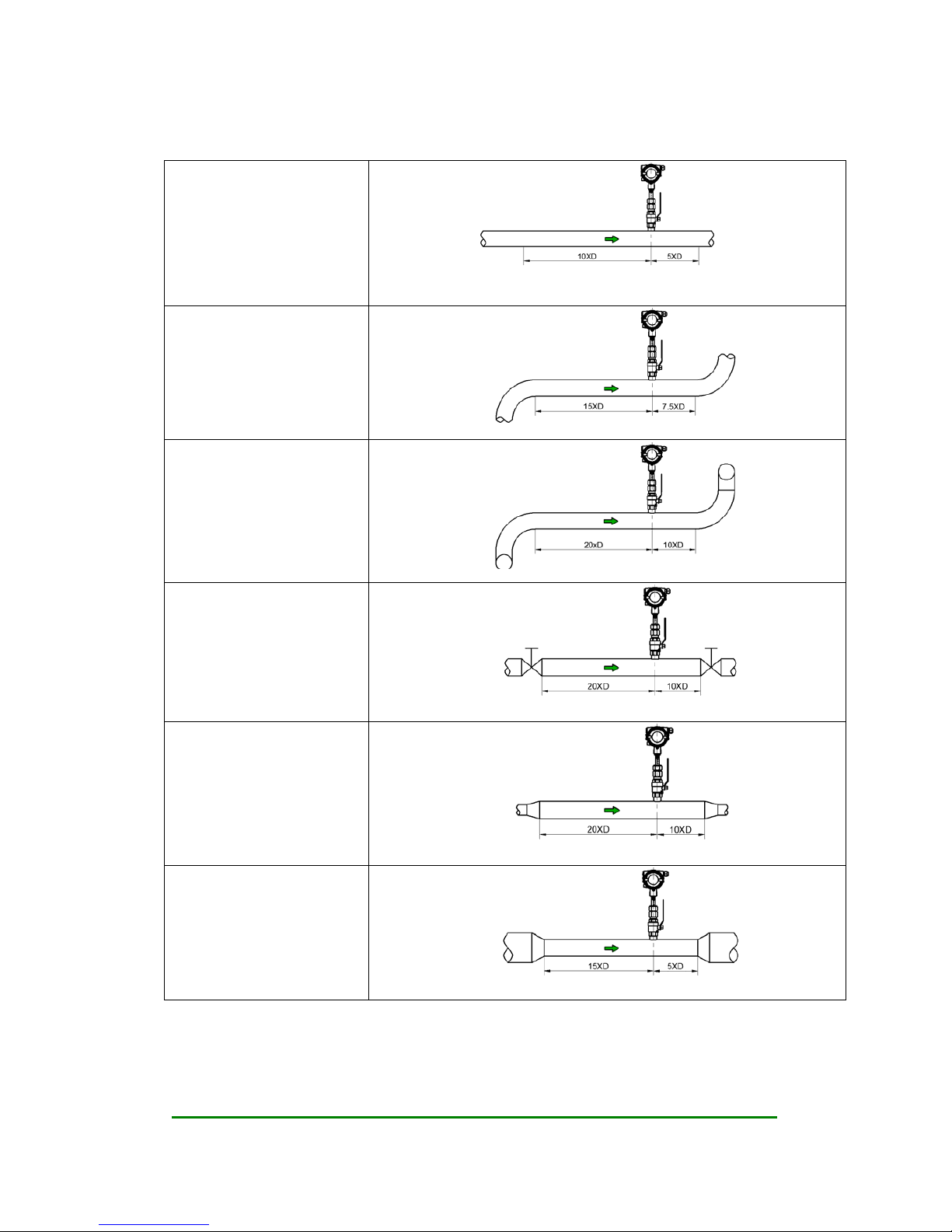
2.2 Requirement on straight pipe line
Standard
Curved pipe line in the
upstream or downstream
Curved pipe line that may creat
turbulence in the upstream or
downstream
There are valves or pressure
controller or any other device
may cause turbulence in
upstream or down stream of the
flowmeter
If the pipeline of the flowmeter
is upsized
If the pipeline of the flowmeter
is downsized
User’s Manual Rev1.0
Date:15/07/2015 User’s Manual
9/47
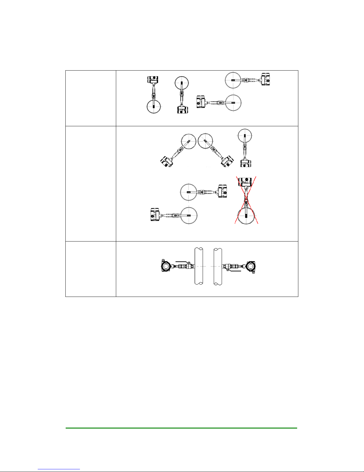
2.3 Requirement on insertion direction
On a horizontal
pipe line, normal
air or gas
Above or under the pipeline Side of the pipe line
On a horizontal
pipe line, high
humidity air or wet
natural gas.
45 degree under the pipe line or just under the pipelien
On the side of the pipe. Do not recommend to install the meter above the
pipeline
On a vertical
pipeline, when the
density of the gas is
higher than air

User’s Manual Rev1.0
Date:15/07/2015 User’s Manual
10/47
2.4 Procedure of installation
2.4.1 Nut sleeve insertion (No flow in pipeline)
1) Drill a hole on the position where the meter will be installed, Ø 13mm (± 0.5 mm)
2) Clean the burrs and sharps on where will be welded
3) Weld the MNPT 1/2” socket (Part No.1) on the open hole vertically. The socket and the open hole
should be concentric, and vertical to the center line of the pipe line
4) Connect the 1/2” ball valve (Part No.2) with FNPT threads on both ends to the socket. Seal the
thread connection with thread sealant. Please note the lever on the ball valve should be point to up
when the valve is open
5) Insert the flowmeter into the ball valve and the socket, connect the sleeve (Part No.3) on the meter
and the ball valve, seal the thread conection part with thread sealant. Tighten the nut (Part No.4) with
hand.
6) Calculate the insertion depth. The sensor should be in the middle of the pipe area, insertion
depth S=A/2+B+C. Please reference to the picture below
A: Inner diameter of the pipeline
B: Thickness of the pipe line
C: The distance between the top of the pipeline and the upper end of the nut when the nut is fixed
Table of contents
Other Nitto Measuring Instrument manuals


