MSI A320M-A PRO User manual

1
Contents
Contents
2
3
5
6
LAN Port LED Status Table........................................................................................6
7
CPU Socket.................................................................................................................8
DIMM Slots..................................................................................................................9
PCI_E1~2: PCIe Expansion Slots................................................................................9
JFP1, JFP2: Front Panel Connectors.......................................................................10
SATA1~4: SATA 6Gb/s Connectors...........................................................................10
ATX_PWR1, CPU_PWR1: Power Connectors...........................................................11
CPU_FAN1, SYS_FAN1: PWM Fan Connectors .......................................................11
JUSB1, JUSB2: USB 2.0 Connectors........................................................................12
JUSB3: USB 3.2 Gen1 Connector .............................................................................12
JAUD1: Front Audio Connector ................................................................................13
JCOM1: Serial Port Connector.................................................................................13
JTPM1: TPM Module Connector...............................................................................13
JCI1: Chassis Intrusion Connector...........................................................................14
JBAT1: Clear CMOS (Reset BIOS) Jumper...............................................................14
15
Entering BIOS Setup.................................................................................................15
Resetting BIOS..........................................................................................................16
Updating BIOS...........................................................................................................16
17
Installing Windows® 10.............................................................................................17
Installing Drivers......................................................................................................17
Installing Utilities .....................................................................................................17
Thank you for purchasing the MSI® mother-
board. This User Guide gives information about board layout,
component overview, BIOS setup and software installation.

2
The components included in this package are prone to damage from electrostatic
discharge (ESD). Please adhere to the following instructions to ensure successful
computer assembly.
Ensure that all components are securely connected. Loose connections may cause
the computer to not recognize a component or fail to start.
Hold the motherboard by the edges to avoid touching sensitive components.
It is recommended to wear an electrostatic discharge (ESD) wrist strap when
handling the motherboard to prevent electrostatic damage. If an ESD wrist strap is
not available, discharge yourself of static electricity by touching another metal object
before handling the motherboard.
Store the motherboard in an electrostatic shielding container or on an anti-static
pad whenever the motherboard is not installed.
Before turning on the computer, ensure that there are no loose screws or metal
components on the motherboard or anywhere within the computer case.
Do not boot the computer before installation is completed. This could cause
permanent damage to the components as well as injury to the user.
If you need help during any installation step, please consult a certified computer
technician.
Always turn off the power supply and unplug the power cord from the power outlet
before installing or removing any computer component.
Keep this user guide for future reference.
Keep this motherboard away from humidity.
Make sure that your electrical outlet provides the same voltage as is indicated on
the PSU, before connecting the PSU to the electrical outlet.
Place the power cord such a way that people can not step on it. Do not place
anything over the power cord.
All cautions and warnings on the motherboard should be noted.
If any of the following situations arises, get the motherboard checked by service
personnel:
Liquid has penetrated into the computer.
The motherboard has been exposed to moisture.
The motherboard does not work well or you can not get it work according to
user guide.
The motherboard has been dropped and damaged.
The motherboard has obvious sign of breakage.
Do not leave this motherboard in an environment above 60°C (140°F), it may
damage the motherboard.

3
Supports 1st, 2nd and 3rd Gen AMD Ryzen™ / Ryzen™ with
Radeon™ Vega Graphics and 2nd Gen AMD Ryzen™ with
Radeon™ Graphics / Athlon™ with Radeon™ Vega Graphics
and A-series / Athlon X4 Desktop Processors for Socket AM4
AMD® A320 Chipset
2x DDR4 memory slots, support up to 32GB*
Support 1866/ 2133/ 2400/ 2667(OC)/ 2933(OC)/
3200(OC)+ MHz
Dual channel memory architecture
Supports non-ECC UDIMM memory
Supports ECC UDIMM memory (non-ECC mode)
* Please refer www.msi.com for more information on
compatible memory.
1x PCIe 3.0 x16 slot
Supports x16 speed with 1st, 2nd and 3rd Gen AMD
Ryzen™ processors
Supports x8 speed with Ryzen™ with Radeon™ Vega
Graphics and 2nd Gen AMD Ryzen™ with Radeon™
Graphics processors
Supports x4 speed with AMD® Athlon™ with Radeon™
Vega Graphics Processors
1x PCIe 2.0 x1 slot
1x DVI-D port, supports a maximum resolution of
1920x1200@60Hz*
1x HDMI™ port 1.4, supports a maximum resolution of
4096x2160@30Hz*
* Only support when using AMD® Ryzen™ with Radeon™ Vega
Graphics and 2nd Gen AMD Ryzen™ with Radeon™ Graphics/
Athlon™ with Radeon™ Vega Graphics Processors
* Maximum shared memory of 2048 MB
AMD® A320 Chipset
4x SATA 6Gb/s ports
Supports RAID 0, RAID 1 and RAID 10
Continued on next page
4
Continued from previous page
AMD® A320 Chipset
6x USB 3.2 Gen1 (SuperSpeed USB) (4 Type-A ports on the
back panel, 2 ports available through the internal connectors)
6x USB 2.0 (High-speed USB) ports (2 Type-A ports on the
back panel, 4 ports available through the internal connectors)
Realtek® ALC892 Codec
7.1-Channel High Definition Audio
LAN 1x Realtek 8111H Gigabit LAN controller
1x PS/2 keyboard port
1x PS/2 mouse port
1x DVI-D port
1x HDMI™ port
4x USB 3.2 Gen1 Type-A ports
1x LAN (RJ45) port
2x USB 2.0 Type-A ports
3x Audio jacks
1x 24-pin ATX main power connector
1x 4-pin ATX 12V power connector
4x SATA 6Gb/s connectors
1x USB 3.2 Gen1 connector (supports additional 2 USB 3.2
Gen1 ports)
2x USB 2.0 connectors (supports additional 4 USB 2.0 ports)
1x 4-pin CPU fan connector
1x 4-pin system fan connector
1x Front panel audio connector
1x Serial port connector
2x Front panel connectors
1x TPM module connector
1x Chassis Intrusion connector
1x Clear CMOS jumper
NUVOTON NCT5565 Controller Chip
Continued on next page

5
Continued from previous page
CPU/System temperature detection
CPU/System fan speed detection
CPU/System fan speed control
m-ATX Form Factor
8.9 in. x 7.4 in. (22.6 cm x 18.7 cm)
1x 128 Mb flash
UEFI AMI BIOS
ACPI 6.1 , SM BIOS 2.8
Multi-language
Drivers
SUPER CHARGER
COMMAND CENTER
LIVE UPDATE 6
SMART TOOL
X-BOOST
CPU-Z MSI GAMING
Google Chrome™, Google Toolbar, Google Drive
Norton™ Internet Security Solution
Please check the contents of your motherboard package. It should contain:
Motherboard
Driver DVD
Quick Installation Guide
I/O Shielding
SATA 6G Cable
Case Badge
Product Registration Card
If any of the above items are damaged or missing, please contact your retailer.
6
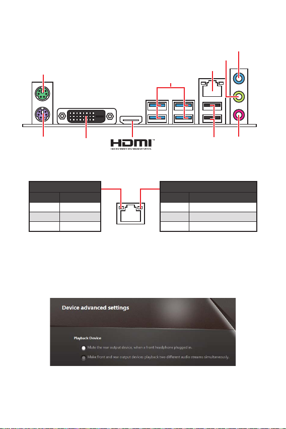
Off No link
Yellow Linked
Blinking Data activity
Off 10 Mbps connection
Green 100 Mbps connection
Orange 1 Gbps connection
PS/2 Keyboard
PS/2 Mouse LAN
DVI-D USB 2.0
USB 3.2 Gen1
Line-in
Mic in
Line-out
To configure 7.1-channel audio, you have to connect front audio I/O module to JAUD1
connector and follow the below steps.
Click on the to open the dialog
below.
Select .
Plug your speakers to audio jacks on rear and front I/O panel. When you plug into
a device at an audio jack, a dialogue window will pop up asking you which device
is current connected.
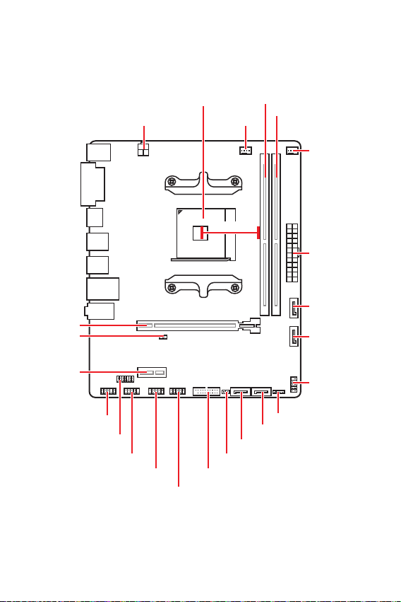
7
PCI_E1
JBAT1
PCI_E2
ATX_PWR1
JCOM
JUSB2
JUSB3
JUSB1
JCI1
JFP1
SATA4
SATA3
SATA2
SATA1
JFP2
JAUD1
JTPM1
CPU Socket
CPU_PWR1
DIMMA1
DIMMB1
SYS_FAN1
CPU_FAN1
52.00mm*
* Distance from the center of the CPU to the nearest DIMM slot.
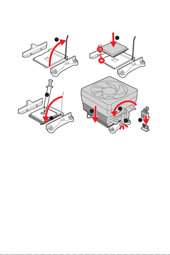
8
Please install the CPU into the CPU socket as shown below.
1
3
5
4
6
7
8
2
Always unplug the power cord from the power outlet before installing or removing
the CPU.
Please retain the CPU protective cap after installing the processor. MSI will deal
with Return Merchandise Authorization (RMA) requests if only the motherboard
comes with the protective cap on the CPU socket.
When installing a CPU, always remember to install a CPU heatsink. A CPU heatsink
is necessary to prevent overheating and maintain system stability.
your system.
Overheating can seriously damage the CPU and motherboard. Always make sure
the cooling fans work properly to protect the CPU from overheating. Be sure to apply
an even layer of thermal paste (or thermal tape) between the CPU and the heatsink to
enhance heat dissipation.
If you purchased a separate CPU and heatsink/ cooler, Please refer to the docu-
mentation in the heatsink/ cooler package for more details about installation.
9
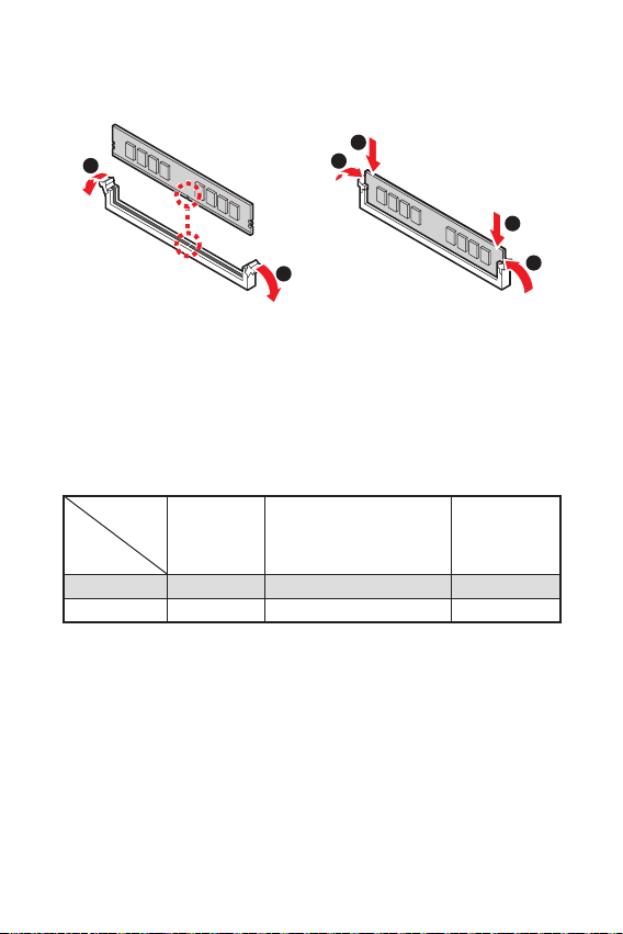
Please install the memory module into the DIMM slot as shown below.
1
1
2
3
3
2
Due to chipset resource usage, the available capacity of memory will be a little less
than the amount of installed.
Please note that the maximum capacity of addressable memory is 4GB or less
for 32-bit Windows OS due to the memory address limitation. Therefore, we recom-
mended that you to install 64-bit Windows OS if you want to install more than 4GB
memory on the motherboard.
Processors
Slots
1st, 2nd and
3rd Gen AMD
Ryzen™
Ryzen™ with Radeon™
Vega Graphics/ 2nd Gen
AMD Ryzen™ with Radeon™
Graphics and A-series/
Athlon X4
Athlon™ with
Radeon™ Vega
Graphics
PCI_E1 PCIe 3.0 x16 PCIe 3.0 x8 PCIe 3.0 x4
PCI_E2 PCIe 2.0 x1 PCIe 2.0 x1 PCIe 2.0 x1
If you install a large and heavy graphics card, you need to use a tool such as MSI
Gaming Series Graphics Card Bolster to support its weight to prevent deformation
of the slot.
unplug the power supply power cable from the power outlet. Read the expansion
card’s documentation to check for any necessary additional hardware or software
changes.
10
These connectors are SATA 6Gb/s interface ports. Each connector can connect to one
SATA device.
SATA4
SATA2 SATA3
SATA1
Please do not fold the SATA cable at a 90-degree angle. Data loss may result
during transmission otherwise.
SATA cables have identical plugs on either sides of the cable. However, it is
saving purposes.
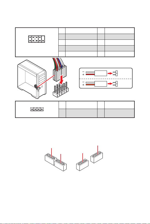
These connectors connect to the switches and LEDs on the front panel.
1
2 10
9
JFP1
1 HDD LED + 2 Power LED +
3 HDD LED - 4 Power LED -
5 Reset Switch 6 Power Switch
7 Reset Switch 8 Power Switch
9 Reserved 10 No Pin
1
JFP2
1 Speaker - 2 Buzzer +
3 Buzzer - 4 Speaker +
HDD LED
RESET SW
HDD LED HDD LED -
HDD LED +
POWER LED -
POWER LED +
POWER LED
Table of contents
Languages:
Other MSI Motherboard manuals


MSI
MSI B250M MORTAR ARCTIC User manual

MSI
MSI H110M PRO-VD PLUS User manual

MSI
MSI Z270I GAMING PRO CARBON AC User manual

MSI
MSI MS-6182 User manual

MSI
MSI H310M PRO-C User manual

MSI
MSI MS-9803 User manual

MSI
MSI Intel RAID User manual

MSI
MSI GF615M User manual

MSI
MSI MS-6507 Quick start guide

MSI
MSI MS-7222 User manual


