Microtech e-DIAGNOSTIC User manual

High impact PC casing
Silicone rubber cover
IP 65 rated
LCD backlight graphic display
433.39 MHz bidirectional Transceiver
Operates from 2 x 1.5V AAA batteries
1
Microtech Designs
[email protected]om.au
microtechdesigns.com.au
Specifications
e
-
L
o
o
p
e
-
L
o
o
p
M
i
n
i
Activation and signal strength
1. Press the MENU button and you will see two selections,
Open RX will be highlighted, press SET to select. You can
now monitor the e-Loop activation.
2. When the trip level is exceeded, the screen will display the
activation and the level that it tripped at for 2 seconds, to
exit this mode just press the MENU button again.
3. To test for background interference, press the MENU button,
now scroll using the down arrow until Signal Strength is
displayed. Press SET to select or MENU to exit.
4. Low background noise is indicated as 1 to 2 bars, if you see
more than 2 bars displayed constantly, you may have an
interference problem.
This Signal Strength bar graph will also display the signal
strength from our transmissions of remotes or e-Loops.
Although this will only be a short burst, it can be quite useful
in determining signal strength at the receiver end.
1
2 3
4
2
Microtech Designs
[email protected]om.au
microtechdesigns.com.au
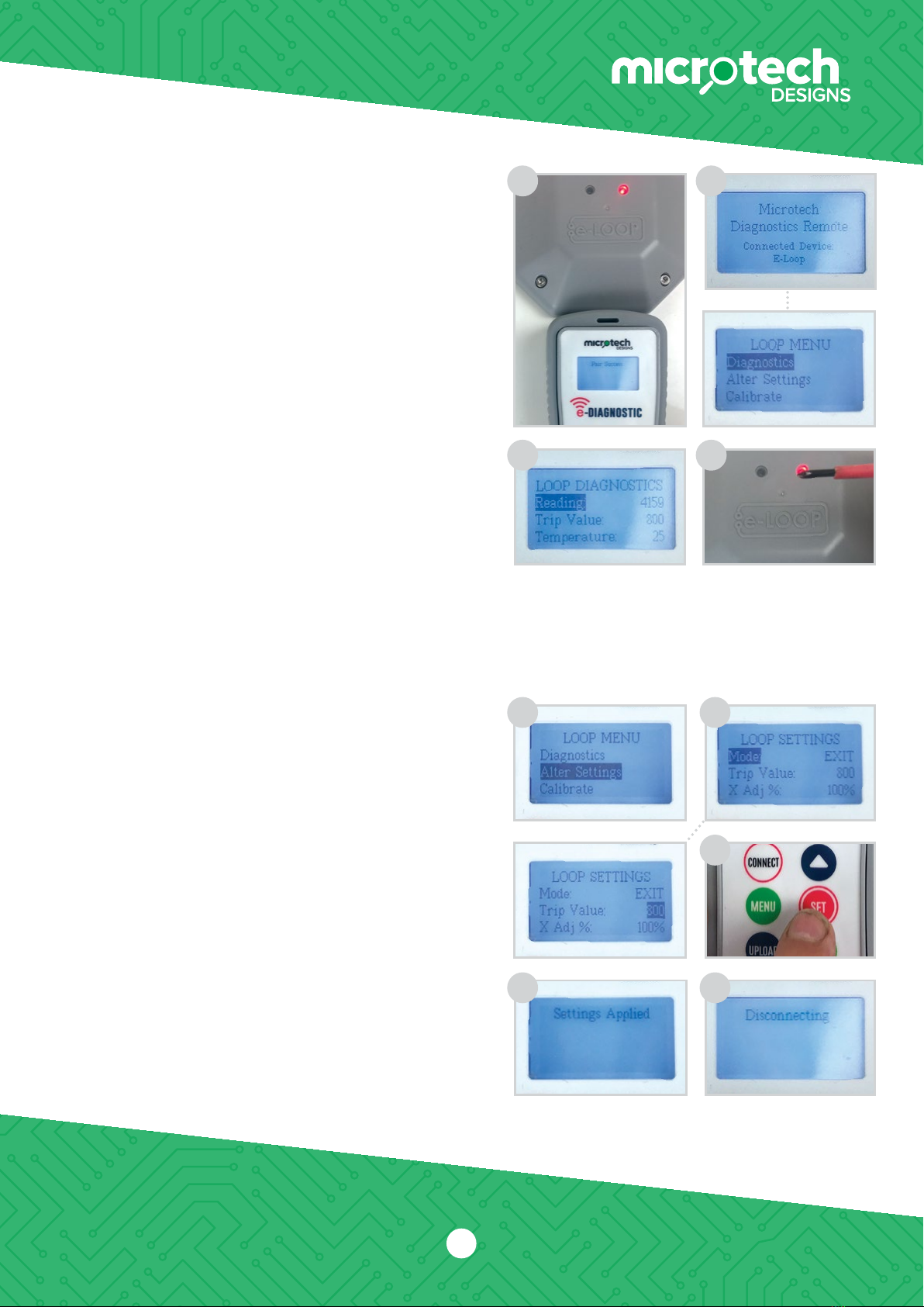
Connecting to an e-Loop
1. Hold the remote close to the e-Loop and press the CONNECT
button. If pairing is successful, Pair Success will display and
the red LED will illuminate on the e-Loop. If not successful, the
screen will display Timeout.
2. Now press the MENU button. Diagnostics will be highlighted,
press the SET button to select.
3. The screen will display the magnetic field:
Reading – This should be sitting between 0-200
when no vehicle is present.
Trip Value – This is the level the reading needs
to reach in order to trigger the e-Loop.
Temperature – this is the ambient temperature of the e-Loop.
4. You can test the e-Loop on the bench by moving a magnetic
screwdriver close to the e-Loop. You will see the reading value
increase until it trips and sends an open command.
5. To disconnect the e-Loop press the CONNECT button.
Altering the e-Loop settings
NOTE: You will need to be connected to the e-Loop to make any
alterations to settings. (Refer to Connecting to an e-Loop
section above).
1. After making connection scroll to Alter Settings.
2. The first selection is Mode – EL00C and EL0IC are preset
to EXIT mode and cannot be changed. EL00C-RAD and
EL0IC-RAD are preset to Presence mode and can be
changed to EXIT mode if required. To change mode press
SET, now use the Up or Down buttons to alter and SET to
confirm. If no further changes need to be made, press the
UPLOAD button to upload the new settings. Once upload
is complete, the screen will display Settings Applied.
3. Second selection is Trip Value; the default is 800 which is
the most sensitive. To change value press SET to highlight
the setting value and use the Up or Down arrow buttons to
increase or decrease value.
4. After the value has been altered press the SET button again.
If no further changes need to be made, press the UPLOAD
button to upload the new settings. Once upload is complete,
the screen will display Settings Applied.
5. To disconnect press the CONNECT button.
1 2
3 4
1
5
2
4
3

3
Altering XYZ axis
NOTE: We only recommend altering the XYZ axis for complex sites
where you need less activation from a particular direction,
such as the exit road being close proximity to an entry road. In
this instance we would reduce the X field direction so that
a passing vehicle in next lane will not trigger the e-Loop.
Z = Vertical detection
Y = Approach and Depart detection (Arrow indication)
X = Left and Right-hand side detection
1. First make a connection to the e-Loop, then go to MENU and
select Alter Settings and press SET. Now scroll to the Axis you
want to change, then press SET again.
2. If we are changing the X axis, you can set a value between
0% to 200% – this is the same for all X, Y and Z axis.
3. Use the Up or Down arrow buttons to change the value,
then press the SET button to confirm.
NOTE: All values should add up to a minimum of 300, so if reducing
one axis then another should be increased to compensate.
4. Now press UPLOAD to confirm the new settings and the screen
will display Sending Settings. Then press the CONNECT button to
disconnect the e-Loop, or MENU button to access other options.
Calibrating the e-Loop using
the diagnostic remote
1. Make a connection to the e-Loop, then press MENU and select
Calibrate. The Calibrate menu screen will have Calibrate Loop
highlighted. Now press SET to calibrate the e-Loop and the
screen will display Calibrating Loop.
2. To uncalibrate the e-Loop enter the Calibrate menu and scroll
down to select Uncalibrate Loop. Now press the SET button,
and the e-Loop is uncalibrated.
Microtech Designs
[email protected]om.au
microtechdesigns.com.au
4
1
2 3
1
2
Radar Read
1. Press SET to read the radar sensor state. If False is shown it
means no object is detected. If True is displayed this means
an object has been detected.
1
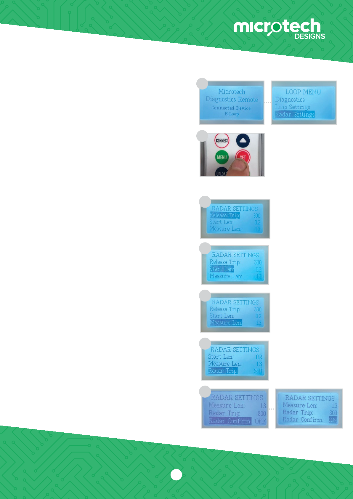
Changing Radar settings
NOTE: Only available for EL00C-RAD and EL0IC-RAD versions. Please
contact technical department before altering any radar settings,
doing so may cause the e-Loop to be unreliable.
1. After making connection, scroll to Radar Settings and press
the SET button.
2. To change any of these settings, navigate to the desired option
using the UP and DOWN buttons, and press the SET button to
select option. Again, use the UP and DOWN buttons to change
the setting and press SET to confirm.
3. Once all changes have been made, press the UPLOAD button
to upload the new settings to the e-Loop. If successful Setting
Applied will display, if not it may display Connection Fail – if this
occurs, try again.
Radar settings:
1. The first setting is Release Trip – this is what the magnetic field
value needs to drop below to trigger the radar to take a reading
which verifies the vehicle is no longer present. 300 is the default
setting and should not be changed before contacting the
technical department.
2. The second setting is Start Lens – this is the distance the radar
will start detecting. 200 is the default setting and should not be
change before contacting the technical department.
3. The third setting is Measure Lens – this is the maximum distance
the radar will detect a vehicle. This can be adjusted depending
on the types of vehicles being used and the location of the
e-Loop.
NOTE: Lowering the range for an undercover car park where no trucks
can enter can extend battery life. Extending range for a trucking
depo may be needed for high trailer detection.
4. The fourth option is Radar Trip – this is used to adjust the
sensitivity of the radar. The higher the number, the less sensitive
it will be. 500 is the default setting and should not be changed
before consulting the technical department.
5. The fifth option is Radar Confirm – the default is OFF when
turned on. The sensor will detect the vehicle with magnetic field
detection and will then confirm with radar before sending Open
command.
Press SET to alter. Use Up or Down buttons to change and SET
to confirm. If no further changes need to be made, press the
UPLOAD button to upload the new settings. Once upload is
complete, the screen will display Settings Applied.
4
Microtech Designs
[email protected]om.au
microtechdesigns.com.au
1
2
1
2
3
4
5
Microtech Designs
microtechdesigns.com.au
enquiries@microtechdesigns.com.au
5
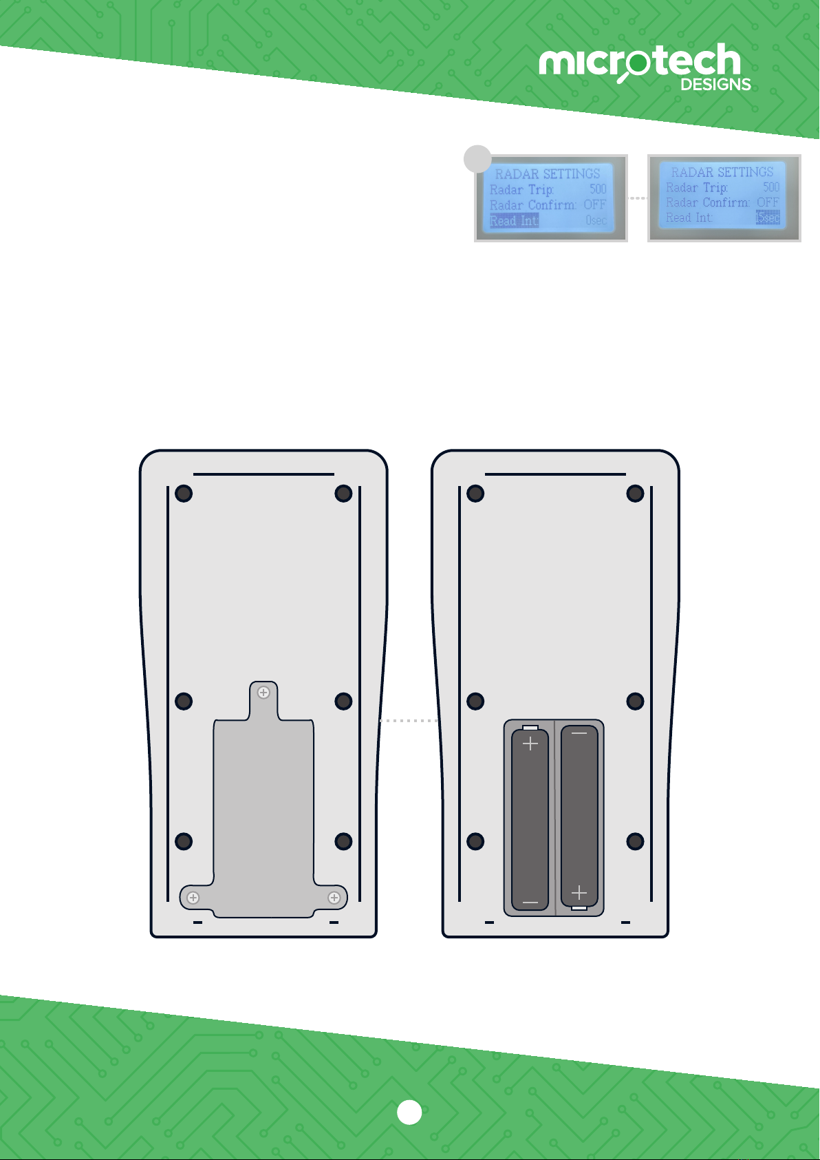
6. The sixth option is Radar INT - this is used to adjust the time
between radar reads when in precesnse mode. The default value is
60 seconds, and can be adjusted from 15 to 180 seconds.
6
Press SET to alter. Use Up or Down buttons to change and SET
to confirm. If no further changes need to be made, press the
UPLOAD button to upload the new settings. Once upload is
complete, the screen will display Settings Applied.
Batteries
In order to replace the two AAA batteries, rst remove the three screws on the back of the device.
Then remove the plate, and replace the two batteries. Then reinstall the plate and screws.
Table of contents
Other Microtech Measuring Instrument manuals

Microtech
Microtech 120125131 User manual

Microtech
Microtech 110180027 User manual

Microtech
Microtech 14109805 Series User manual

Microtech
Microtech 1106500258 User manual

Microtech
Microtech 110184008 User manual

Microtech
Microtech 110181027 User manual

Microtech
Microtech 120126131 User manual

Microtech
Microtech 110180254 User manual

Microtech
Microtech SUB-MICRON 1250511006 User manual


