Megger Baker AWA-IV User manual

Megger Limited
Archcliffe Road
Dover
Kent
T: +44 (0)1 304 502101
F: +44 (0)1 304 207342
Megger GmbH
Obere Zeil 2 61440
Oberursel,
GERMANY
T: 06171-92987-0
F: 06171-92987-19
Megger USA - Valley Forge
Valley Forge Corporate Center
2621 Van Buren Avenue
Norristown
Pennsylvania, 19403
USA
T: 1-610 676 8500
F: 1-610-676-8610
Megger Limited
Archcliffe Road
Dover
Kent
CT17 9EN
ENGLAND
T: +44 (0)1 304 502101
F: +44 (0)1 304 207342
Megger USA - Dallas
4271 Bronze Way
Dallas TX 75237-1019
USA
T: +1 800 723 2861 (USA only)
T: +1 214 333 3201
F: +1 214 331 7399
E: ussales@megger.com
Megger AB
Rinkebyvägen 19, Box 724,
SE-182 17
DANDERYD
T: 08 510 195 00
E: seinfo@megger.com
Megger Baker Instruments
4812 McMurry Avenue, Suite 100
Fort Collins, CO 80525
USA
T: +1 970-282-1200
F: +1 970-282-1010
E: baker.sales@megger.com
E: baker.tech-support@megger.com
Manufacturing Sites
Megger Head Office
This instrument is manufactured in the United States.
The company reserves the right to change the specification or design without prior notice.
Megger is a registered trademark.
Microsoft and Windows are either registered trademarks or trademarks of Microsoft Corporation in the United States
and/or other countries.
© Megger Limited 2018 www.megger.com
Baker AWA-IV
Static Motor Analyzer
Quick Reference Guide
Part number: 71-050 EN V3

Baker AWA-IV Static Motor Analyzer
Quick Reference Guide
Part number: 71-050 EN
Revision: V3
Publication date: December 2018
Copyright Megger.
All rights reserved. No part of this handbook may be copied by photographic or other means
unless Megger have before-hand declared their consent in writing. The content of this handbook is
subject to change without notice.
Megger cannot be made liable for technical or printing errors or shortcomings of this handbook.
Megger also disclaims all responsibility for damage resulting directly or indirectly from the delivery,
supply, or use of this matter.
Baker AWA -IV Static Motor Analyzer www.megger.comi

This equipment has been tested and found to comply with the limits for a Class A
digital device, pursuant to Part 15 of the FCC rules. These limits are designed to provide
reasonable protection against harmful interference with the equipment is operated in its
installation.
This equipment generates, uses, and can radiate radio frequency energy and, if
not installed and used in accordance with the product manual, could cause harmful
interference to radio communications. If this equipment does cause harmful interference,
the user will be required to correct the interference.
Due to the phenomena being observed and the material properties being measured, this
equipment radiates radio frequency energy while in the active test mode. Care should be
taken to ensure this radio frequency energy causes no harm to individuals or other nearby
equipment.
Never exceed maximum operating capabilities of the Baker AWA-IV tester, power packs,
or the Baker ZTX accessory. If using the equipment in any manner not specified by
Megger, the protection provided by the equipment may be impaired.
Be sure to comply with all safety procedures prescribed by your organization, industry,
and governing standards. Failure to heedsafety precautions can result in injury or death
from severe electrical shock.
Additional information reference
The Baker AWA-IV Quick Reference Guide is intended to introduce users to the analyzer and its
basic operating procedures.
For complete safety information anddetailed information on the device, end-user license agreement,
and CE conformity refer to the Baker AWA-IV User Manual.
WARNING
CAUTION
NOTICES
www.megger.com ii

1. INSTRUMENT DESCRIPTIONS...............................................................................................
Baker AWA-IV 2 kV/4 kV model front panel................................................................................
Baker AWA-IV 6 kV/12 kV model front panel..............................................................................
2. PREPARING FOR TESTING....................................................................................................
Process overview........................................................................................................................
Creating or opening a database.................................................................................................
Selecting a motor to test............................................................................................................
Creating a new Motor ID............................................................................................................
Creating a new Test ID................................................................................................................
Selecting tests and setting up test parameters.............................................................................
3. BASIC TESTING PROCEDURES.............................................................................................
Using the Explore, Motor ID, and Route tabs to find motors.......................................................
Running tests automatically, semi-automatically, or manually......................................................
Test sequence.............................................................................................................................
Reviewing test results/data.........................................................................................................
Printing reports..........................................................................................................................
1
1
3
4
4
4
5
5
7
10
16
16
18
20
23
26
Table Of Contents
Baker AWA -IV Static Motor Analyzer www.megger.comiii
1. Instrument Descriptions
Baker AWA-IV 2 kV/4 kV Model Front Panel
All Baker AWA-IV series analyzers feature an eight-inch touch screen with a graphical user interface.
The interface features a logical layout of touch icons that improve ease of use.
Each tester’s voltage capacity is identified by the markings found just below the touch screen.
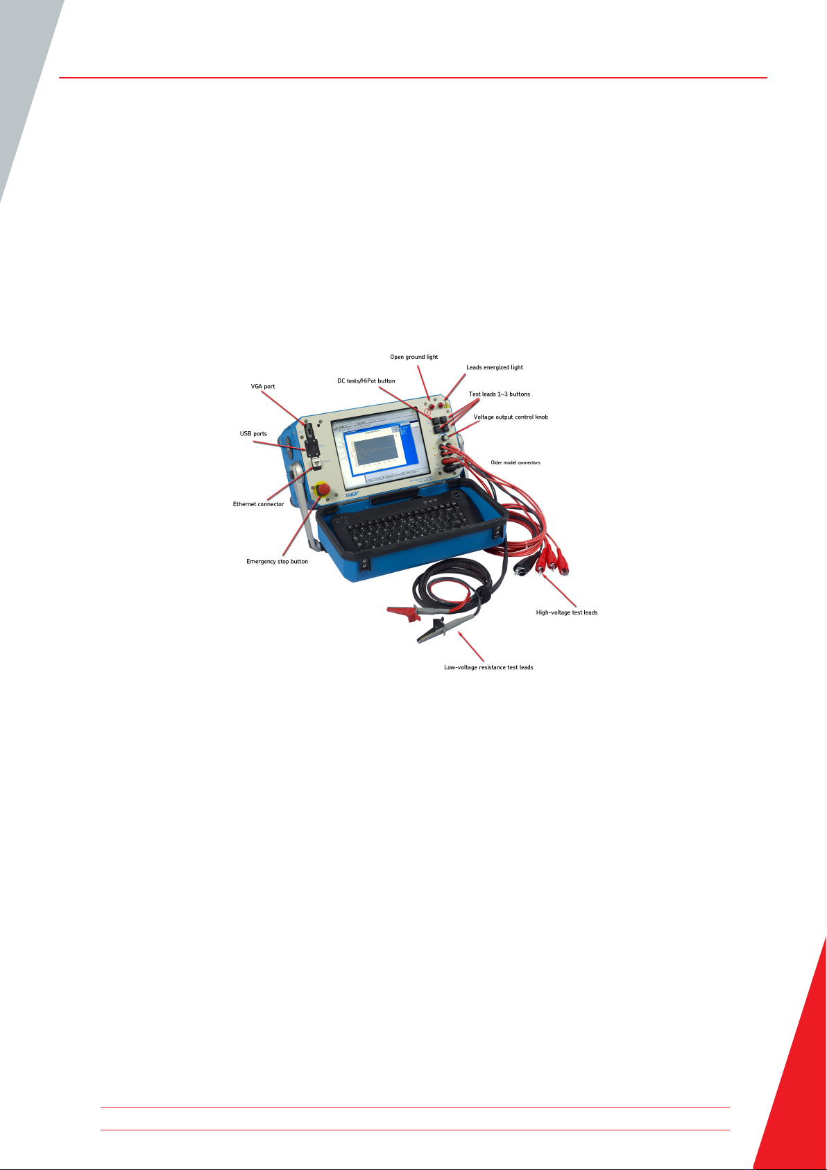
Figure 1. Front panel controls for AWA-IV 2 kV and 4 kV models.
VGA port
The VGA port is used to connect the tester to a larger monitor (not included) foreasier viewing of
test results.
USB ports
Industry standard USB ports are accessible from the front panel for connections to aprinting device,
and data storage and retrieval devices.
Ethernet connector
The tester can be connected to a network via the ethernet connector.
Equipment stop button
This large, highly visible red button is easily pressed for immediate termination of high-voltage
testing. It disconnects all high voltages from the test leads.
Instrument Descriptions
www.megger.com 1
Instrument Descriptions
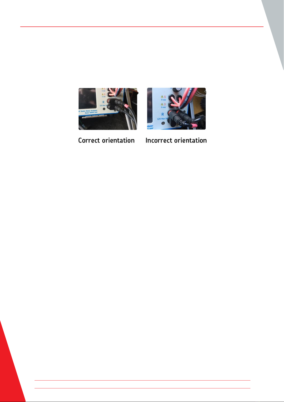
Low-voltage resistance test leads
Both sides of the connection clips must be in contact with the terminal of the motor being
measured. Most recent AWA-IV 2/4kV testers have two low-voltage resistance test leads. Ensure
that the leads are connected as shown in the example below.
Figure 2. Proper orientation of AWA-IV 2/4 kV 2-lead connectors.
AWA-IV6 analyzers use the high-voltage leads for low-voltage resistance testing (no additional set
of leads).
AWA-IV 12kV analyzers have three red test leads for low-voltage resistance testing (no black lead).
High-voltage test leads
The Baker AWA-IV uses high-voltage test leads for surge, Baker ZTX, and DC testing. You must
keep the leads clean and dry for best measurement performance.
The AWA-IV 6 KV model differs from the AWA-IV 12 kV with respect to test leads and procedures
for use.
The AWA-IV 6 kV analyzer uses only one set of leads for both high- and low-voltage testing; it does
not include a separate set of low-voltage test leads (shown as “low voltage resistance test leads” in
the image).
Voltage output control knob
Turn the knob clockwise to increase the applied voltage or counterclockwise to decrease the
voltage.
The rate of voltage increase or decrease is set via the touch screen interface.
Do not force the knob; turning the knob harder does not cause voltage to ramp any quicker and
may damage the instrument.
Baker AWA -IV Static Motor Analyzer www.megger.com2

BAKER AWA-IV 6 KV/12 KV MODEL FRONT PANEL
Figure 3. Front panel controls for Baker AWA-IV 6 kV and 12 kV models.
It is important to note that test lead clips have exposed metal areas.
Do not touch the clips while tests are running. Always exercise care
to ensure the clips are not placed in proximity to the frame or ground
potential.
Instrument Descriptions
CAUTION
www.megger.com 3

2. Preparing For Testing
PROCESS OVERVIEW
The basic process for testing a motor on the AWA-IV includes the following steps:
1. Open an existing database or create a new one.
2. Select an existing motor to test, or create a new motor (motor ID and test ID)
3. Select tests to run.
4. View and confirm test parameters, or modify test parameters.
5. Run tests automatically, semi-automatically, or manually.
Each step is described in more detail in this chapter.
CREATING OR OPENING A DATABASE
1. Start the Baker AWA-IV application by clicking on the icon on the tester screen or the MS
Windows Start button.
2. Click on the appropriate radio button for creating a new database or opening an existing one.
Figure 4. Dialog box for creating or opening a database.
3. When creating a new database, a dialog box will open so you can name the new database.
Enter the database name in the field then click OK.
4. When opening an existing database, highlight the database needed from the list and click OK.
Preparing For Testing
Baker AWA -IV Static Motor Analyzer www.megger.com4
Preparing For Testing
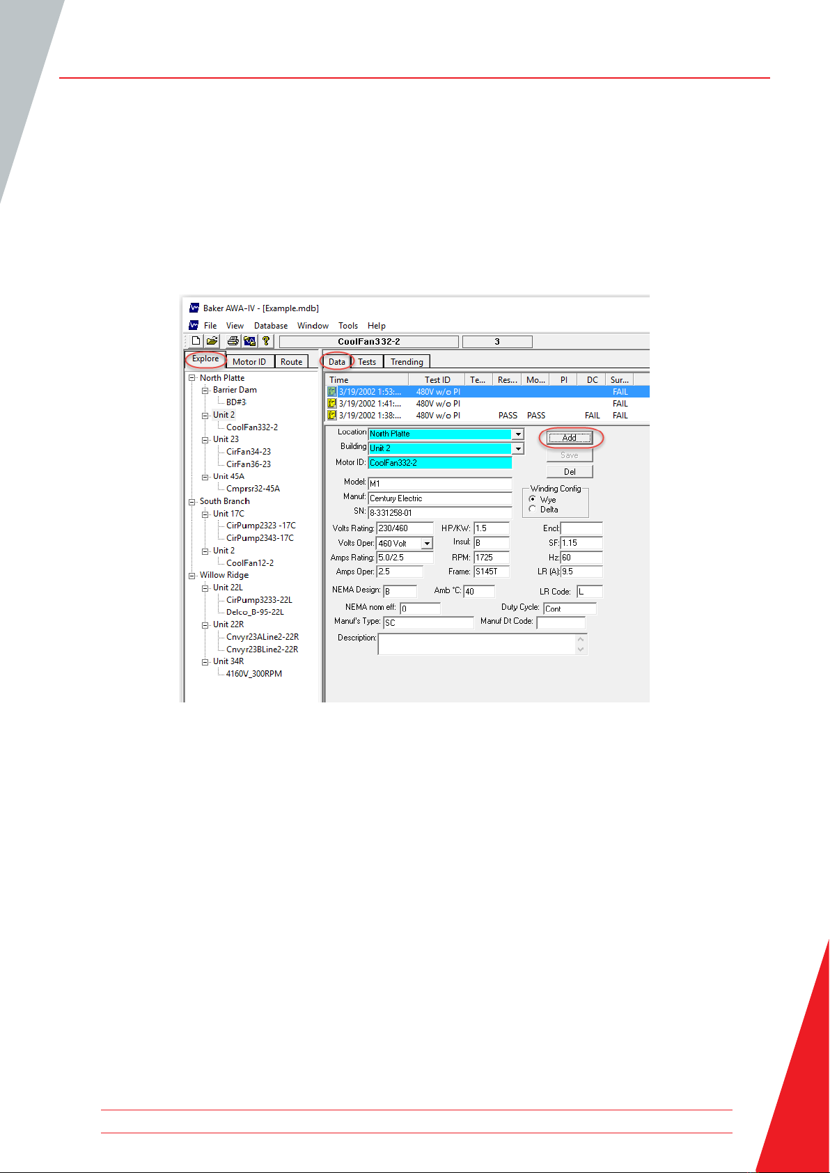
SELECTING A MOTOR TO TEST
1. Click on the Data tab to select existing motors, or to create and store information for new
motors. Each motor will be listed in the Explore tab’s Motor Tree on the left side of the screen.
The Motor Tree provides a complete listing of all motors stored in a particular database.
2. To select the Motor ID for an existing motor, locate it within the Explore tab then click on the
Motor ID to highlight it and to load its information in the Data tab.
Figure 5. Using the Data tab to create a new motor.
CREATING A NEW MOTOR ID
1. If the motor you are testing does not yet have a Motor ID in the system, you will need to create
a new Motor ID. To add a new Motor ID to the selected database, click on the Add button.
2. Click on the Clear button to remove all information currently entered in the fields.
3. Type the Motor ID, Location, Building, and name plate information in the appropriate fields.
www.megger.com 5
Other manuals for Baker AWA-IV
1
Table of contents
Other Megger Measuring Instrument manuals

Megger
Megger Baker DX Series User manual

Megger
Megger DCM1500S User manual

Megger
Megger MPQSIM User manual

Megger
Megger DET10C User manual

Megger
Megger TORKEL 910 User manual

Megger
Megger PCA2 User manual

Megger
Megger TDR1000/3 User manual

Megger
Megger PAM410 User manual

Megger
Megger LCR131 User manual

Megger
Megger HV DAC-300 User manual

Megger
Megger frax 99 User manual

Megger
Megger Surgeflex 8-1000 User manual

Megger
Megger DLRO10HD User manual

Megger
Megger DCM305E User manual

Megger
Megger Ducter DLRO2 User manual

Megger
Megger VF3 User manual

Megger
Megger DCM310 User manual

Megger
Megger DCM1500 User manual

Megger
Megger BT51 User manual

Megger
Megger MOM200A User manual


