
Marmitek IP EYE ANYWHERE 241 - ADVANCED User manual

20377 / 20110202 • IP EYE ANYWHERE 241/341™
ALL RIGHTS RESERVED MARMITEK ©
P
EYE ANYWHE
R
Advanced Installation Guide
IP EYE ANYWHERE™
IP EYE ANYWHERE 241/341

IPEyeAnywhere 241 / 341TM 1
Preface
Thank you for purchasing the Marmitek H.264/MPEG4/MJPEG
Day&Night or True Colour Megapixel Network Camera, a
standalone system that can be connected directly to an Ethernet
or Fast Ethernet network.
Equipped with a megapixel CMOS sensor, the camera allows you
to capture a wider field of view with a resolution of up to 1280 x
1024. With support for latest H.264 technology, you can record
streaming video that utilizes high quality H.264 images to your
hard drive, enable motion detection and setup automated e-mail
alerts for security.
With the Infrared LEDs and light sensor on the camera (IPEA 241
only), you can capture clear images even in the dark environment.
Compared to the conventional PC Camera, this camera features a
built-in CPU and web-based solutions that can provide a cost-
effective solution to transmit the real-time high-quality video
images and sounds synchronously for monitoring. The camera
can be managed remotely, so that you can use a web browser to
access and control it from any desktop/notebook computer over
the Intranet or Internet.
The simple installation procedures and web-based interface allow
you to integrate it into your network easily. With comprehensive
applications supported, the IPEyeAnywhere 241 / 341 is your best
solution for remote monitor, high quality, and high performance
video images.

©MARMITEK
2
This Advanced Installation Guide provides you with the
instructions and illustrations on how to use your camera, which
includes:
Chapter 1 Introduction to Your Camera describes the features
of the camera. You will also know the components
and functions of the camera.
Chapter 2 Hardware Installation helps you install the camera
according to your application environment. You can
use this camera at home, at work, at any where you
want.
Chapter 3 Accessing the Camera lets you start using your
camera without problem. The camera can be set up
easily and work within your network environment
instantly.
Chapter 4 Configuring the Camera guides you through the
configuration of the camera using the Web browser on
your PC.
Chapter 5 Appendix provides the specification of the camera
and some useful information for using your camera.
NOTE The illustrations and configuration values in this guide are for
reference only. The actual settings depend on your practical
application of the camera.

IPEyeAnywhere 241 / 341TM 3
Contents
CHAPTER 1 ............................................................................................ 5
INTRODUCTION TOYOUR CAMERA ............................................................... 5
1.1 CHECKING THE PACKAGE CONTENTS ...................................5
1.2 GETTING TO KNOW YOUR CAMERA......................................6
1.3 FEATURES AND BENEFITS ...................................................10
1.4 SYSTEM REQUIREMENT.......................................................13
CHAPTER 2 .......................................................................................... 14
HARDWARE INSTALLATION......................................................................... 14
2.1 INSTALLING THE CAMERA STAND.......................................14
2.2 CONNECTING THE CAMERA TO LAN/WLAN .....................15
2.3 APPLICATIONS OF THE CAMERA..........................................16
CHAPTER 3 .......................................................................................... 17
ACCESSING THE CAMERA ......................................................................... 17
3.1 USING IPFINDER .................................................................17
3.2 ACCESSING TO THE CAMERA ..............................................18
3.3 CONFIGURING THE IP ADDRESS OF THE PC ........................21
CHAPTER 4 .......................................................................................... 22
CONFIGURING THE CAMERA ...................................................................... 22
4.1 USING THE WEB CONFIGURATION ......................................22
4.2 QUICK SETUP ......................................................................23
4.3 BASIC SETUP .......................................................................30
4.4 NETWORK SETTINGS ...........................................................33
4.5 SETTING UP VIDEO &AUDIO ..............................................41
4.6 EVENT SERVER CONFIGURATION........................................46
4.7 MOTION DETECT .................................................................52
4.8 EVENT CONFIGURATION .....................................................53
4.9 TOOLS .................................................................................56
4.10 USB ....................................................................................58
4.11 INFORMATION .....................................................................60
Appendix ............................................................................................ 61
A.1 SPECIFICATION ....................................................................61

©MARMITEK
4
SAFETY WARNINGS
• To prevent short circuits, this product should only be used inside
and only in dry spaces.
• Do not expose the components to rain or moisture. Do not use
the product close to a bath, swimming pool etc.
• Do not expose the components of your systems to extremely
high temperatures or bright light sources.
• In case of improper usage or if you have altered and repaired the
product yourself, all guarantees expire. Marmitek does not accept
responsibility in the case of improper usage of the product or when
the product is used for purposes other than specified. Marmitek
does not accept responsibility for additional damage other than
covered by the legal product responsibility.
• This product is not a toy. Keep out of reach of children.
• Do not open the product: the device may contain live parts. The
product should only be repaired or serviced by a qualified expert.
• Only connect the adapter to the mains after checking whether
the mains voltage is the same as the values on the identification
tags. Never connect an adapter when it is damaged. In that case,
contact your supplier.

IPEyeAnywhere 241 / 341TM 5
CHAPTER 1
INTRODUCTION TOYOUR CAMERA
1.1 Checking the Package Contents
Check the items contained in the package carefully. You should
have the following:
5One IPEyeAnywhere 241 / 341 Network Camera
5One AC Power Adapter
5One Camera Stand
5One External Antenna
5One Ethernet Cable (RJ-45 type)
5One Installation CD-ROM
5One Quick Installation Guide
NOTE Once any item contained is damaged or missing, contact the
authorized dealer of your locale.
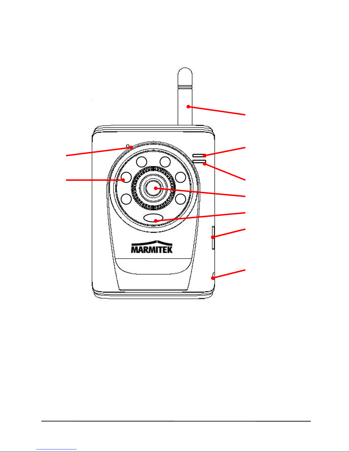
1.2 Getting to Know Your Camera
Front / Right Panel
h
©MARMITEK
6
a. Infrared LEDs (x6) allow your camera to capture clear image
in a dark environment (IPEA 241 only).
b. Light Sensor is used to trigger on and off the Infrared LEDs
according the environmental light level.(IPEA 241 only)
c. Lens Assembly
b
c
a
d
f
g
e
i

IPEyeAnywhere 241 / 341TM 7
d. USB Port allows you to connect an external USB device. It
provides the power distribution up to 500mA.
e. Internal Microphone allows the camera to receive sound and
voice.
f. Link LED indicates the camera’s network connectivity with the
flashing green light.
g. Power LED indicates the camera is powered on with the
steady amber light.
h. External Antenna
i. USB* Unmount Button Is used to remove the connected
USB device safely.
NOTE After long pressing the Unmount button for four seconds, the
Power LED starts flashing. When the Power LED resumes the
steady amber light, you can remove the USB device safely.
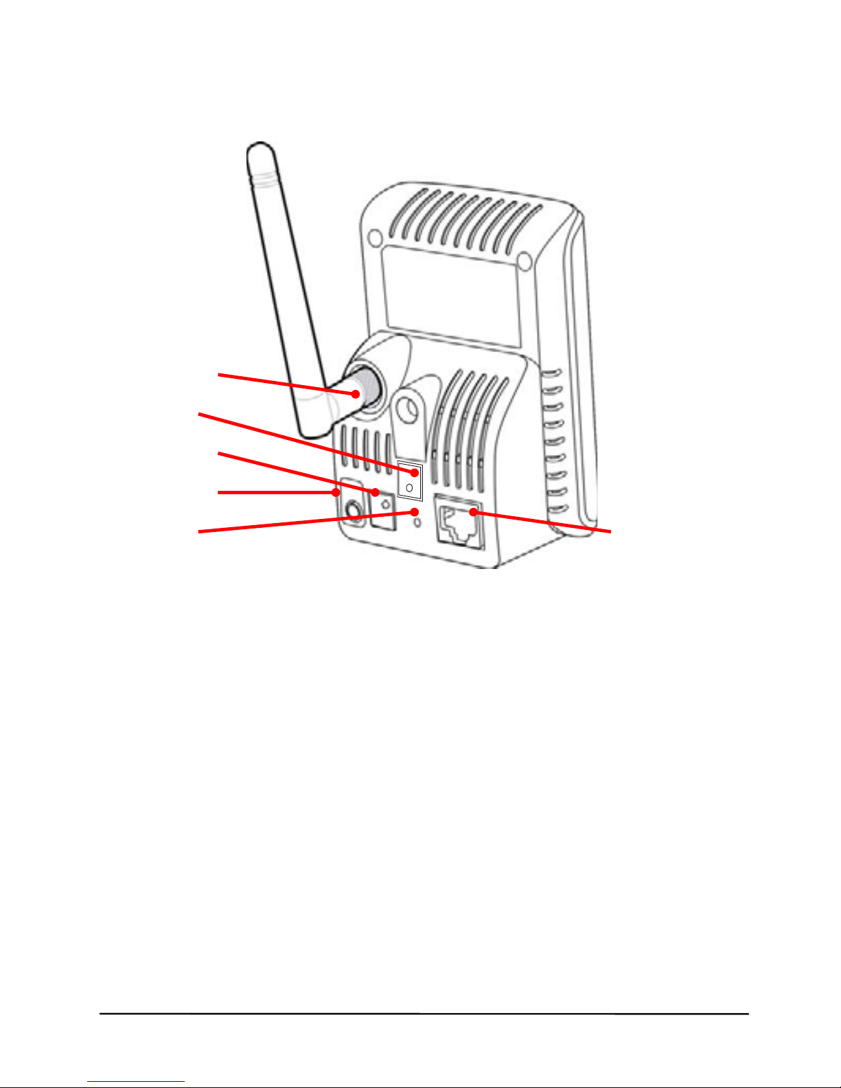
Rear Panel
m
k
©MARMITEK
8
j. DC Power Connector connects the AC power adapter, in
order to supply power to the camera.
k. WPS Button is used to protect your WLAN. Instead of
entering the network name (SSID), your wireless network can
be protected simply by pushing a button.
TIP For more information of using the WPS button, refer to the
instruction of the Web Configuration, Network >> Wireless >>
WPS Setting.
l. Reset Button will restart the camera when it is pressed
quickly; when it is pressed and held for five seconds, the
camera will resume the factory default settings.
m. Wireless Antenna Connector is used to attach the external
antenna.
o
j
ln

IPEyeAnywhere 241 / 341TM 9
n. Ethernet Cable Connector connects the network cable,
which supports the NWay protocol so that the camera can
detect the network speed automatically.
o. Audio-out Connector connects an external active speaker.
Other manuals for IP EYE ANYWHERE 241 - ADVANCED
1
This manual suits for next models
2
Table of contents
Other Marmitek IP Camera manuals

Marmitek
Marmitek IP EYE ANYWHERE 10 User manual

Marmitek
Marmitek IP RoboCam541 User manual

Marmitek
Marmitek IP EYE ANYWHERE 241 - ADVANCED User manual

Marmitek
Marmitek robodome10 User manual

Marmitek
Marmitek IP EYE ANYWHERE 10 User manual

Marmitek
Marmitek IP RoboCam User manual

Marmitek
Marmitek IP Robocam 8 wireless Original operating instructions

Marmitek
Marmitek IP EYE ANYWHERE 10 - SOFTWARE ULTRAVIEW Safety guide

Marmitek
Marmitek IP EYE ANYWHERE - SOFTWARE ULTRAVIEW Safety guide

Marmitek
Marmitek ROBODOME 10 - QUICK User manual


