
LARTET DC-24S User manual
1600K23B
TETRALEC E.I. S.L.
USER MANUAL
DC-24 and DC-25
Thermometer and hygrometer


Content
1. INTRODUCTION AND GENERAL CHARACTERISTICS......................................................................... 1-1
1.1. Characteristics of the DC-24 and DC-25 displays............................................................................1-2
1.2. Temperature and humidity sensor characteristics............................................................................ 1-2
1.3. Weight of the displays....................................................................................................................... 1-3
1.4. Dimensions of the DC-24 and DC-25...............................................................................................1-3
1.4.1. Dimensions of the DC-24S and DC-25S..................................................................................1-3
1.4.2. Dimensions of the DC-24D and DC-25D..................................................................................1-3
1.4.3. Dimensions of the sensor case................................................................................................. 1-3
1.5. Display mounting..............................................................................................................................1-4
1.5.1. Mounting of the DC-24S and DC-25S......................................................................................1-4
1.5.2. Mounting of the DC-24D and DC-25D...................................................................................... 1-5
2. INSTALLATION......................................................................................................................................... 2-1
2.1. Accessing inside the display.............................................................................................................2-1
2.2. Powering the display.........................................................................................................................2-1
2.3. Serial line connection........................................................................................................................2-2
2.4. Placing the sensor............................................................................................................................2-2
3. OPERATION. ............................................................................................................................................ 3-1
3.1. Initial reset. ....................................................................................................................................... 3-1
3.1.1. Displays with several sensors................................................................................................... 3-1
3.2. Programming parameters................................................................................................................. 3-1
3.2.1. Modify parameters RS-485, Ethernet or Wifi............................................................................3-2
3.3. RS-485 parameters. ......................................................................................................................... 3-3
3.3.1. Parameter 1 for RS-485: Address of the display......................................................................3-3
3.3.2. Parameter 2 for RS-485: Serial line configuration.................................................................... 3-3
3.3.3. Parameter 3 for RS-485: Sensor control and communication protocol....................................3-4
3.3.4. Parameter F: Exit menu............................................................................................................3-4
3.4. Parameters Ethernet and Wifi. .........................................................................................................3-5
3.4.1. Parameter 1 for Ethernet and Wifi: MAC address of the display..............................................3-5
3.4.2. Parameter 2 for Wifi: Load the IP configuration through the RS-232 port................................3-5
3.4.3. Parameter 3 for Ethernet and Wifi: Sensor control and communication protocols................... 3-5
3.4.4. Parameter 4 for Ethernet and Wifi: Load the default port configuration in the Ethernet or Wifi
port. ..................................................................................................................................................3-5
3.4.5. Parameter F: Exit menu............................................................................................................3-5
4. COMMUNCATION PROTOCOLS............................................................................................................. 4-1
4.1. ASCII protocol for RS-485................................................................................................................4-1

4.1.1. Displays DC-24/X. Read values from the display.....................................................................4-2
4.1.2. Displays DC-25/X. Send values to the display.........................................................................4-2
4.2. PROTOCOL MODBUS RTU - ASCII for RS-485.............................................................................4-4
4.3. PROTOCOL MODBUS RTU - Word for RS-485.............................................................................. 4-6
4.4. TCP/IP, UDP/IP PROTOCOL........................................................................................................... 4-8
4.4.1. UDP protocol ............................................................................................................................4-8
4.4.2. Read values from the display ................................................................................................... 4-8
4.4.3. Send values to the display. Displays without sensor................................................................4-9
4.5. ModBus/TCP PROTOCOL.............................................................................................................4-10
4.5.1. Modbus/TCP protocol.............................................................................................................4-10
4.5.2. Read data from the display.....................................................................................................4-10
4.5.3. Send temperature and humidity .............................................................................................4-11
4.1. IP Address. Ethernet option............................................................................................................4-13
4.2. Modifying the port settings..............................................................................................................4-13
4.2.1. UDP/IP configuration..............................................................................................................4-14
4.3. IP address. Wifi...............................................................................................................................4-15
4.3.1. Accessing Wifi module configuration...................................................................................... 4-17
4.4. Set up IP Address using the DeviceInstaller. .................................................................................4-20
4.5. Modifying the port settings..............................................................................................................4-20
CHAPTER 1
INTRODUCTION AND GENERAL CHARACTERISTICS
1-1
DC-24 and DC-25 operation manual
1. INTRODUCTION AND GENERAL CHARACTERISTICS
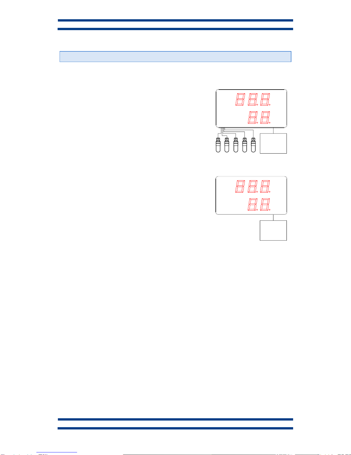
Numerical displays DC-24 and DC.21 are temperature and humidity displays.
DC-24 displays admit form 1 to 5 sensors, calculating the
mean value of all them. It automatically detects the number of
sensors and displays its state once the display is initialized.
The temperature and humidity sensor is placed in a case that
permits a very easy installation using the support included in
the package. The recommended position of the sensor is at
1,7m from the floor. The display can include RS-485, Ethernet
or Wifi connectivity as options.
DC-25 displays are aesthetically identical to the DC-24 but do
not have sensor. They must receive the data from RS-485,
Ethernet or Wifi.
°C
%
OPTIONS:
RS-485
Ethernet
WIFI
°C
%
RS-485
Ethernet
WIFI

1-2
INTRODUCTION AND GENERAL CHARACTERISTICS
CHAPTER 1
DC-24 and DC-25 operation manual
1.1. Characteristics of the DC-24 and DC-25 displays
Supply Voltage...........................................88 to 264 VAC 47 to 63Hz.
Consumption DC-24S and DC-25S..........12VA.
Consumption DC-24S and DC-25S..........24VA.
Display .......................................................7 segments, 100mm high + decimal point.
.....................................................................LED colour red, blue, white or green depending on
.....................................................................the model
.....................................................................Viewing distance: max 50 meters.
Text .............................................................Silkscreen.
Environmental Conditions........................Operation Temperature: -20 to 60ºC.
.....................................................................Storage temperature: -30ºC to 70ºC.
.....................................................................Humidity: 5-95% RH non condensing.
.....................................................................Maximum environmental illumination: 1000 lux.
.....................................................................Sealing: IP41 .
1.2. Temperature and humidity sensor characteristics.
Temperature sensor
Resolution..........................................0.1°C
Precision ............................................±0.5° at 25°C
Response time...................................20s
Working range ...................................-20°C to 80°C
Humidity sensor
Resolution..........................................1%
Precision ............................................±3.5% between 30% and 70%
Response time...................................4 s
Environmental Conditions.....................Sealing: IP65 .
CHAPTER 1
INTRODUCTION AND GENERAL CHARACTERISTICS
1-3
DC-24 and DC-25 operation manual
1.3. Weight of the displays.
The weight of the DC-24S and DC-25S is 5kg.
The weight of the DC-24D and DC-25D is 7kg.
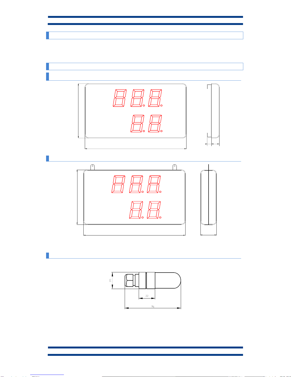
1.4. Dimensions of the DC-24 and DC-25.
1.4.1. Dimensions of the DC-24S and DC-25S.
°C
%
520
320
40
22
1.4.2. Dimensions of the DC-24D and DC-25D.
°C
%
520
320
80
1.4.3. Dimensions of the sensor case
The dimensions of the sensor case in mm are:
1-4
INTRODUCTION AND GENERAL CHARACTERISTICS
CHAPTER 1
DC-24 and DC-25 operation manual
1.5. Display mounting
1.5.1. Mounting of the DC-24S and DC-25S.
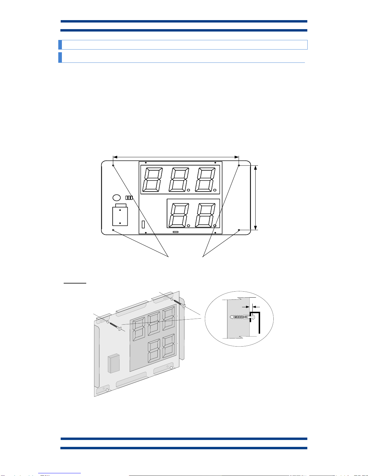
The DC-24S and DC-25S displays can be fixed to the wall in two ways:
1–Hanged. Place 2 of the supplied plug at 410mm from one to the other. Insert the
screws leaving their head outside for 4mm. Hang the display using the upper-side zig-zag.
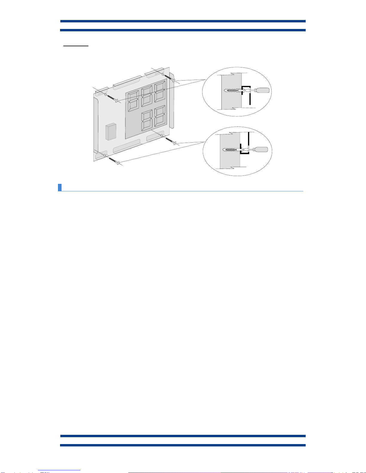
2–Screwed. Remove the methacrylate cover. Place the 4 supplied plugs at the distance
showed in the drawing. Place the 2 upper screws, leaving their head outside for 4 mm. Hang the
display using the upper-side zig-zag. Place the lower screws Tighten all the screws. Replace
the methacrylate cover.
The screws and plugs are provided with the display
4 Fixation Points
410
289
Hanged:
4 mm
PARED
CHAPTER 1
INTRODUCTION AND GENERAL CHARACTERISTICS
1-5
DC-24 and DC-25 operation manual
Screwed:
1.5.2. Mounting of the DC-24D and DC-25D.
The DC-24D and DC-25D displays must be hanged using the rings the display has. Cables
or chains can be used
The power cables and the sensor can be fixed to the mounting elements without tightening
them.
IN ANY WAY THE POWER OR THE SENSOR CABLES CAN BE USED FOR HANGING
THE DISPLAY
PARED

This manual suits for next models
3
Table of contents
Other LARTET Measuring Instrument manuals


