Kurt HDHL6 Instruction Manual
HDHL6 Manual
Hydraulic Assembly
Operating Instruction Manual
HDHL6 (English) & HDHLM6 (Metric)
ENGLISH

TABLE OF CONTENTS
Introduction ................................................................................................................. 3
Setup Instructions ........................................................................................................ 4
Operating Instructions .............................................................................................9-17
HDHL6 Parts List.......................................................................................................... 18
HDHL6 Mechanical Drawing ...................................................................................... 19
Maintenance Schedule ......................................................................................... 20-21
Troubleshooting Tips ................................................................................................. 22
VISE DATA
Use this to fill out information about your vise for quick reference.
Purchase Date: _________ -________ -_________
Purchase Order: ______________________________
______________________________
______________________________
Purchased From:
Delivery Date:
Serial No.: ______________________________
NOTE: MAKE SURE TO REGISTER YOUR WARRANTY ONLINE AT
KURTWORKHOLDING.COM
TABLE OF CONTENTS
Maintenance Log/Notes ............................................................................................ 23
Warranty .................................................................................................................... 24
Vise Installation Instructions ............................ ............................................................ 5
2
Hydraulic Setup ......................................................................................................... 6-8
3
3 | ENLGISH
Table of Contents
Introduction .................................................................................................................3
Setup Instructions......................................................................................................4
Operating Instructions .........................................................................................5-7
DX6 Parts List ...............................................................................................................8
DX6 Mechanical Drawing........................................................................................9
Maintenance Schedule....................................................................................10-12
Troubleshooting Tips ............................................................................................. 13
Vise Data
Use this to ll out information about your vise for quick reference.
Purchase Date: _______ -_______- _______
Purchase Order: _______________________
Purchased From: _______________________
Delivery Date: _______________________
Serial No.: _______________________
Note:
Make sure to register your warranty online at kurtworkholding.
Introduction
Thank you for purchasing a Kurt DX6 vise. You have just purchased one
of the best machine vises in the industry. The outstanding accuracy
of this product is second to none. Backed by a lifetime warranty, this
product will last forever when used and maintained properly.
The original Kurt Anglock vises are designed for precision clamping on
basic machine tools such as knee-type mills, grinders and machining
centers. They can be used for, but are not limited to, operations like
precision boring, drilling, tapping, grinding & nishing.
The patented Anglock design allows the movable jaw to advance in
such a way that each pound of force forward induces a ½ pound force
downward which minimizes the jaw lift and increases accuracy. This
combined with the needle bearings increases jaw clamping pressure.
Other features include: 80,000 psi ductile iron body, hardened vise bed
& jaw plates, semi-hard steel screw.
Table of Contents Introduction
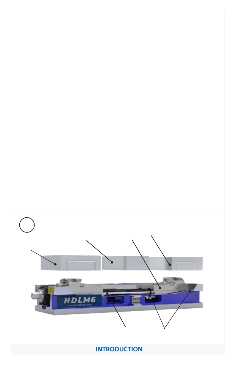
INTRODUCTION
Fig.1
Nut
Screw Screw Brush Seals
Stationary
Jaw
Movable
Jaw
Movable
Jaw
machine tools such as knee-type mills, and machining centers. They can be
used for, but are not limited to, operations like precision boring, drilling,
tapping, & finishing.
The patented Anglock design allows the movable jaw to advance in such a
way that each pound of force forward induces a ½ pound of force downward
which minimizes the jaw lift and increases accuracy. This, combined with
the needle bearings, increases jaw clamping pressure. Other features
include: 80,000 psi ductile iron body, hardened vise bed & jaw plates, and a
semi-hard steel screw.
INTRODUCTION
Thank you for purchasing a Kurt HDHL6 vise. You have just purchased one of
the best machine vises in the industry. The outstanding accuracy of this
product is second to none. Backed by a lifetime warranty against
workmanship and material defects, this product is built to last when used
and maintained properly.
The original Kurt Anglock vises are designed for precision clamping on basic

SET-UP INSTRUCTIONS
Now that you have your new Kurt Vise, it’s time to set-up and begin using it.
You will see that your new vise comes with a Kurt swivel handle. The handle
is specifically designed to provide maximum torque to your vise (clamping
force provided below). Your vise should be mounted to a clean, flat surface.
The surface and the vise must be free of any chips, dirt, or debris of any
kind. The mounting surface can be honed if necessary. Clean the bottom of
the vise with solvent or another cleaner if needed.
To minimize vise bed deflection, clamp your Kurt vise to your machine table,
pallet, or sub-plate using the built-in clamping slots or through the body
holes provided.
Additional clamping can be used, but may not be necessary. Please be sure
to exercise good judgment when securing your vise to the mounting surface.
Be sure your vise is secured and will not move when applying the machine
pressure.
SET-UP INSTRUCTIONS
Torque Ft.-Lbs. Force in Lbs.
10 1540
20 2500
30 3350
40 4300
50 5750
60 6850
70 7450
Hydraulic PSI Force in Lbs.
500 850
1000 1600
1500 2300
2000 3100
2500 3950
3000 4750
3500 5450
Manual Hydraulic
4500
4000 6350
7100
4

Vise Installation Instructions
CAUTION:
Do not attempt to lift the vise by attaching to any of the jaws
or injury may result. Always attach lifting devise to the vise
base frame.
1. Position vise on your machine table, pallet or tombstone using
the .625 or 16 MM locating holes found on the bottom of the vise. We
recommend using the holes that are the farthest apart for better
accuracy.
2. Bolt in place using strap clamps placed on the clamping ledge as
indicated by “Clamp Here” sticker or by bolting directly through the
vise body. When bolting through the body, the stationary jaw must be
removed to gain access to those holes. The outboard holes have plugs
to keep debris out and must be removed if you wish to use those
holes as well. Replace plugs after bolts are secured.
NOTE: Some of the clamp holes are at inch locations and some are at
metric. For exact hole locations, go to pages 16-17 in this manual.
3. After vise is mounted in place, add the vise jaws to the base
assembly. See jaw installation instructions that came with the jaw kit.
If a hard jaw kit “J style” was installed, tram the stationary jaw for
straightness prior to using. If it exceeds .0006” in six inches, remove
stationary jaw and disassemble the 10mm bolt, the tapered top
clamp and .750 dia. split sleeve and clean with solvent and a clean
cloth. Do Not apply grease or oil to these components. Re-assemble
and retest. This should not be necessary when using the carvable
type unless a high degree of accuracy is required and you are not re-
cutting the jaw contour.
INSTALLATION INSTRUCTIONS
5
The HDHL6 Series Hydraulic vises can be paired with one of Kurt's Hydraulic
pumps. You can find all our pump solutions at kurtworkholding.com
Here are instructions for plumbing the HDHL6 vise with the KHP3 air over
hydraulic pump:
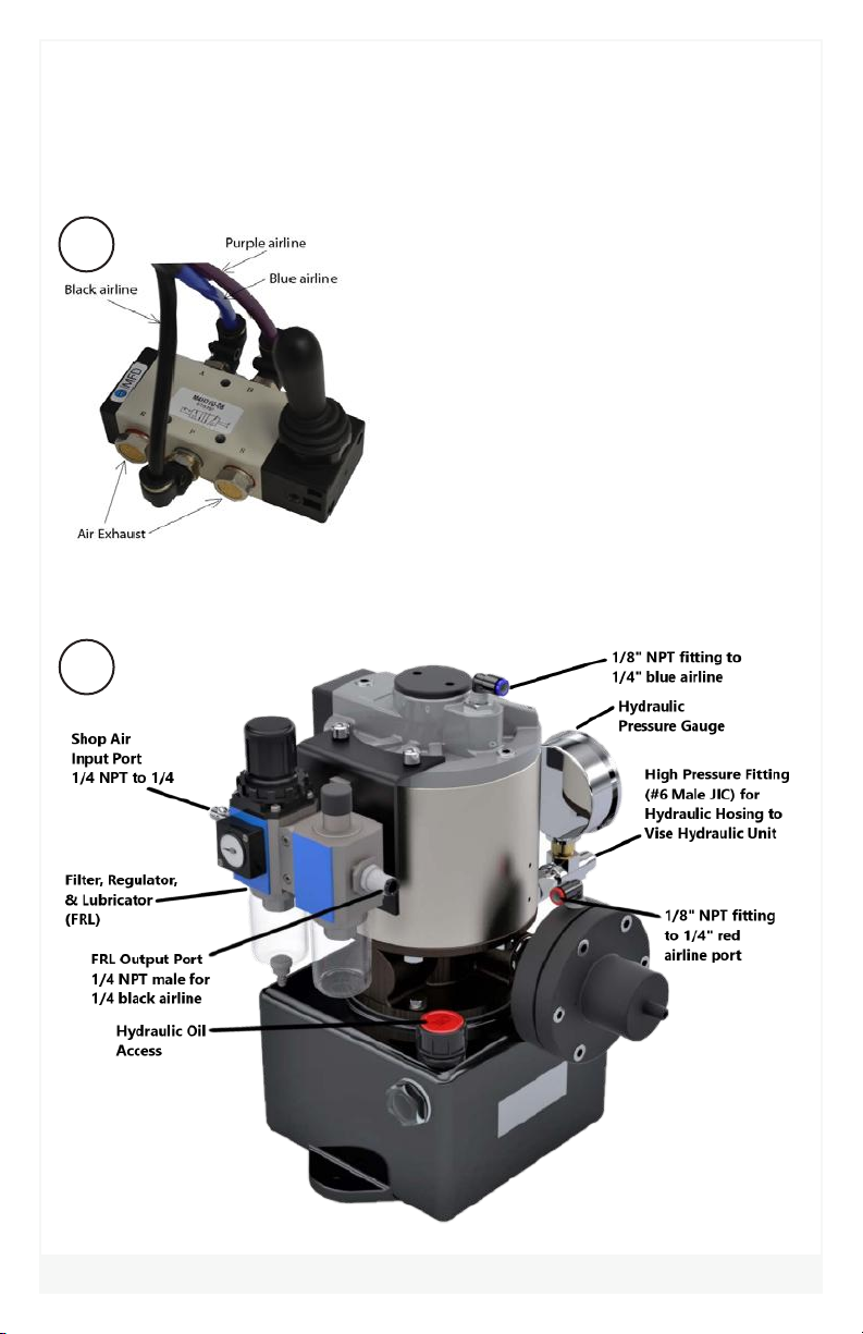
1. Remove plastic caps from pressure and release ports on Hydraulic
pump. Install fittings to the input and output ports (See Fig.4).
2.
3.
4.
Remove plastic caps from pressure and release ports on hand or foot
valve. Install straight fi tting.
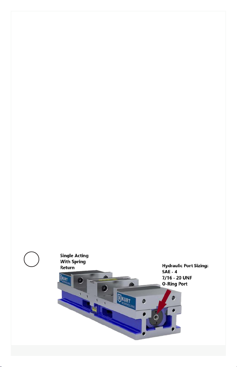
Install a SAE 4 straight fi tting into the 7/16-20 port found on one end
of the vise screw (See Fig.2).
A fi lter-regulator-lubricator combination (See Fig.4) is recommended
to insure clean air coming into the unit. See clamping force chart
(Page 4) for air pressure required to attain desired clamping force.
5. Connect the FRL to the input air line (See Fig.4).
6. Connect the hydraulic line to the hydraulic unit on the HDHL6 vise
and then to the output side of the hydraulic pump(Fig.2 & 4).
7. If using a hand or foot valve connect the 3-line color-coded air line
cluster to the same color ports on the KHP3 pump and valve (Fig.3 &
4).
8. Apply air pressure (80 PSI maximum) to system. Loosen swivel fi tting
at vise and bleed air. Tighten fi tting. Release air pressure.
9. Repeat previous step until all air is purged
10. The KHP3 hydraulic pump will come pre-fi lled with oil (use #13 or
DTE lite if needed)
11. System is now ready for use.
HYDRAULIC SET-UP
OPERATING INSTRUCTIONS
Fig.2
6
OPERATING INSTRUCTIONS
7
Fig.3
HYDRAULIC SET-UP
Fig.4

HYDRAULIC SET-UP
OPERATING INSTRUCTIONS
Jaw Positioning:
Once all plumbing is set up, it time to position jaws for hydraulic clamping.
1. Position jaws less than 1/4 inch from the part being clamped as is
shown in figure 5 above. This is done manually by putting the handle
onto the hex end and turning the screw until the jaws are in position.
2. Make sure the jaws are less than 1/4 inch from the part since the
hydraulic unit has only a 1/4 inch stroke.
3. The vise is now ready to have the hydraulics engaged for clamping
the part.
Fig.5
8

OPERATING INSTRUCTIONS
For proper vise operation, insert the handle on to the hex end of the
vise. Rotate clockwise to clamp and counterclockwise to unclamp your
vise. This handle, combined with the correct amount of torque, will
provide you with all the clamping force you will need to machine your
parts.
DO NOT use any other type of pressure to open or close your vise.
The uses of handle extensions, air impact wrenches, breaker bars, or
hammer strikes are not recommended and will void the warranty if
used. This will also cause damage to the thrust bearing and screw
threads. If you need more clamping force you may require a larger
vise. A torque wrench may be used if set within the torque limits
shown in the tables on page 4.
One-Sided Clamping:
To properly clamp a part in your Kurt double-station vise, you should
place the parts in the center of the jaws resting on the ways of the vise.
Clamping only on one side or above the movable and stationary jaws can
result in jaw lift or loss of accuracy. (See Fig. 6 on page 10)
If one-sided clamping is necessary, you MUST use a dummy part on the
other side. When using parallels or step jaws, you must select a size that
keeps the bottom of the clamped part at or below the top of the
movable and stationary jaws.
Always use jaw plates for clamping. If jaw plates are not used, damage to
the mounting surface of the movable and stationary jaw will occur. This
will result in reduced clamping accuracy and repeatability.
OPERATING INSTRUCTIONS
9
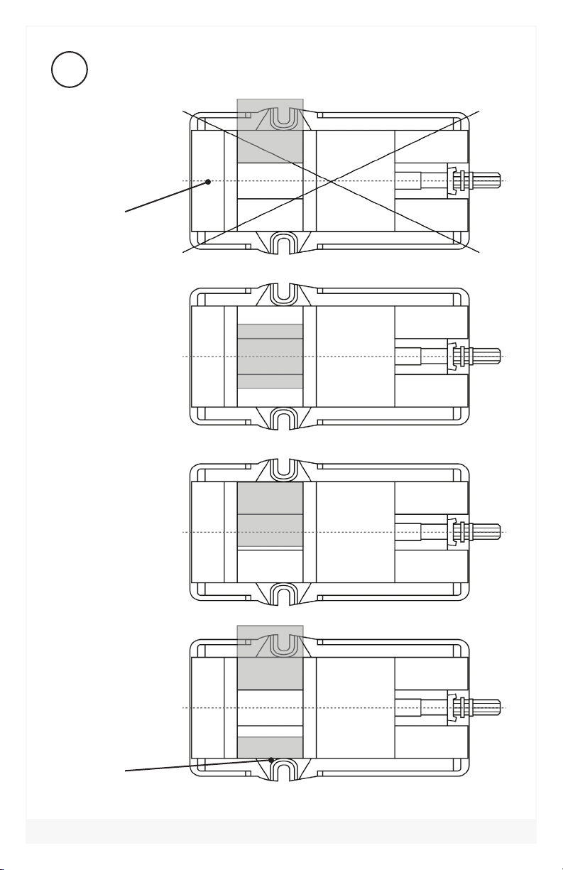
Fig.6
Sketch #2A
Incorrect part
clamping.
Vise width
centerline
Sketch #2B
Correct part
clamping.
Sketch #2C
Correct part
clamping.
Sketch #2D
Correct part
clamping.
Dummy
spacer
OPERATING INSTRUCTIONS 10
Table of contents
Other Kurt Industrial Equipment manuals


