INTEGRA Merering Calec energy master User manual
Installation and operating instructions
CALEC® energy master
The benchmark for energy measurement technology
Short version
Firmware Version 1.00
VD 3-135 e, 05.2019

CALEC®energy master installation and operating instructions 2
1 Contents
1Contents 2
2Information and references 3
2.1 Information 3
2.2 Documents 3
3Safety notices 4
3.1 Symbols used 4
3.2 Intended use 4
3.3 Inappropriate use 4
3.4 Installation guidelines 5
4View of device with protective housing 6
5View of device without protective housing
(Mod) 7
6Mounting the device with protective
housing (Prot) 8
6.1 Scope of supply, tools and mounting
material (Prot) 8
6.2 Installation (Prot) 8
7Mounting the device without protective
housing (Mod) 12
7.1.1Rail mounting 12
7.1.2Connecting to mains power supply
230 VAC 12
7.1.3Connecting to low voltage supply 24
VDC 13
7.1.4Connecting signal cables 13
8Electrical connections 14
8.1 Connection instructions 14
8.2 Wiring diagram, module and signal
numbers 14
8.3 Numbering rules 15
9Operation 16
9.1 PC-Software AMBUS Win II 16
9.2 Display 16
9.2.1Key functions 17
9.3 Right of access, security levels 17
10 Menu overview 18
10.1 Main display and main menu 18
10.2 Submenus 19
11 Use under operating conditions 21
11.1 The main display 21
11.2 The measured values submenu 22
11.2.1 Measured values 22
11.2.2 Meter readings 22
11.2.3 Current values 22
11.2.4 Billing date values 22
11.2.5 Logger values 22
12 Dimensional drawings and technical
specifications 23
12.1 Drawings of device with protective
housing (Prot) 23
12.2 Drawings of device without protective
housing (Mod) 23
25
12.3 Technical specifications 13
Declaration of conformity 28

CALEC®energy master installation and operating instructions 3
2 Information and references
2.1 Information
These installation and operating instructions describe the installation and commissioning of a stan-
dard device. The chapters describe the topics and tasks in the sequence in which they are needed
during commissioning.
•Safety instructions
•Information about the device
•Installation
•Electrical connections
•Operation
•Fault
clearance
•Technical data
Always comply with the safety instructions.
2.2 Documents
The installation and operating instructions VD 3-135 vary in scope, depending on the version and
items covered by the delivery. The information required for ancillary modules and optional functions
is described in additional document extracts (VD 3-136).
Parameterisation software AMBUS Win II
The parameterisation software AMBUS Win II is available for setting the parameters. It can be
downloaded free of charge (see below).
Downloads
The current documents and AMBUS Win II are available as free downloads at
www.aquametro.com /downloads.

4 CALEC®energy master installation and operating
3 Safety notices
3.1 Symbols used
Important information
Non-observance can lead to malfunction.
General warning
Non-observance can lead to damage or malfunction.
Warning of dangerous electric voltage
Non-observance can lead to physical injury!
3.2 Intended use
The device is used as an energy calculator for heating, cooling and air conditioning applications in
district heating or cooling, in building management services and in industrial energy metering.
It is part of a combined heating/cooling or air conditioning meter, consisting of a calculator, a pair of
temperature sensors and a flow meter, or as a transducer for a flow meter.
The environmental conditions described in the technical specifications, as well as the installation and
operating instructions must be complied with.
3.3 Inappropriate use
The device must not be used:
•In explosion-risk zones (no ex-risk protection!)
•In a wet environment (condensing, splashing or dripping water)
•Outdoors, without suitable protection
•In environmental conditions (temperature, humidity, vibrations, electromagnetic in-
terference etc.) that do not comply with the technical specifications
•In all other instances that do not conform to its intended use
The device can be dangerous if it is not used as intended, or not in accordance with the installation
and operating instructions. In order to avoid this, it is essential that the safety instructions, operating
conditions (see technical specifications) and the relevant chapters of these instructions are strictly
adhered to.
The manufacturer accepts no liability for damage arising from inappropriate use.

CALEC®energy master installation and operating instructions 5
3.4 Installation guidelines
The installation should be performed by authorised, skilled personnel, in compliance with
the regulations in force (EN1434 part 6 Regulations and recommendations for installation
and operation) and the recommendations of the industry-specific associations (e.g. the
AGFW series of leaflets on district heating supplies).
The skilled personnel must have read and understood these instructions. The require-
ments in the instructions and the applicable regulations on electrical installations must al-
ways be observed.
Work on electrical circuits with hazardous voltages (> 24 VAC or >42 VDC) may only be
carried out by authorised, skilled people, in compliance with the locally applicable regula-
tions!

6 CALEC®energy master installation and operating
4 View of device with protective housing
Device with closed protective housing
1 Housing cover
2 Operating keys
3 Dot-matrix LCD
4 Type plate with CE marking
5 IR interface on display module
(EN13757-2 / -3 M-Bus)
IrDA interface on CPU module
6 Housing screws, covered by security sealing
caps
Device with opened protective housing
2 Operating keys
3 Display, LCD dot matrix
5 IR interface (EN13757-2 / -3 M-Bus)
IrDA interface
7 Display module
8a Upper terminals, plug-in
8b Lower terminals, plug-in
9 Clip-on holder for modules
10 3 Fastening holes for wall mounting
11 Clip-on holder for rail mounting
12 Strain relief
13 Cover hinges
The wiring diagram is on the inside of the hous-
ing cover.
View of the protective housing from below
11 Clip for rail
14 Cable duct supply 14 mm
15 Cable ducts 10 mm
16 Cable ducts 14 mm

CALEC®energy master installation and operating instructions 7
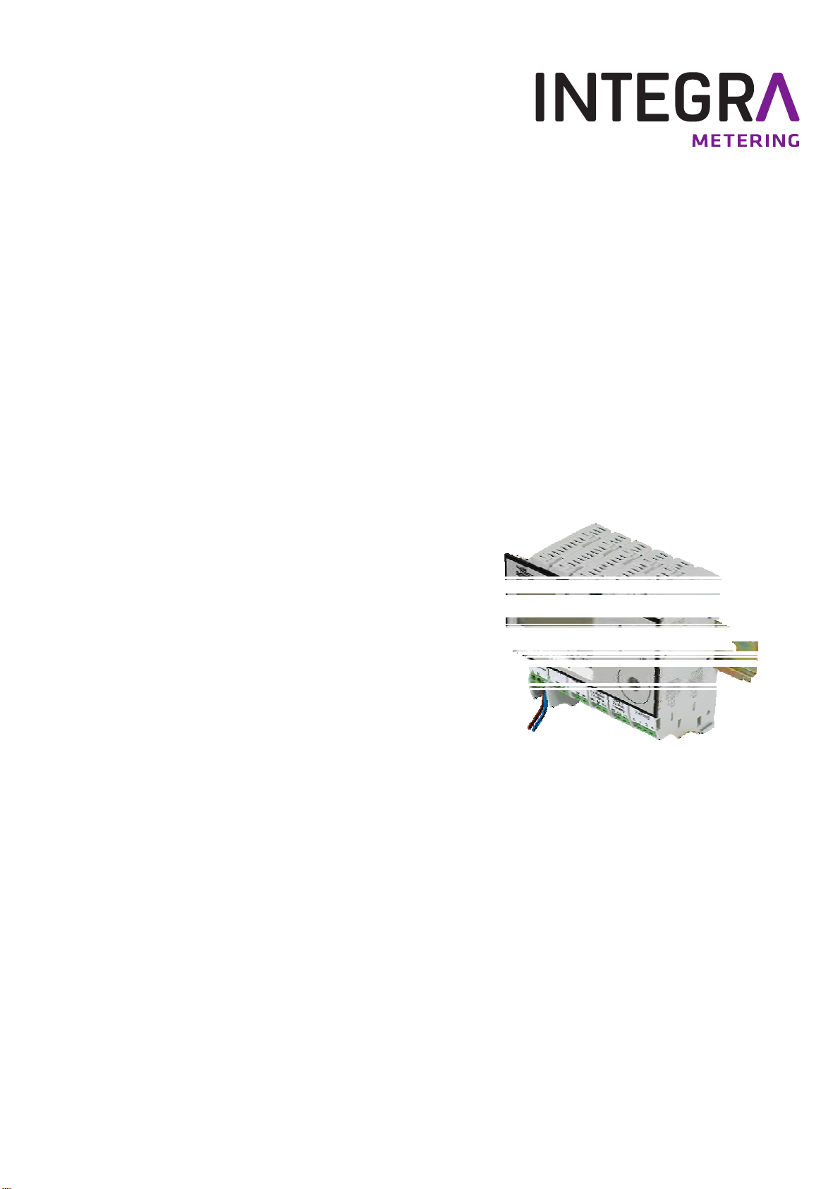
5 View of device without protective housing (Mod)
The following diagram shows the device without protective housing.
2 Operating keys
3 Display, LCD dot matrix
5 IR interface (EN13757-2 / -3 M-Bus)
IrDA interface
7 Display module
8a Upper terminals, plug-in
8b Lower terminals, plug-in
9 Clip-on holder for modules
The Display can be installed at a remote location e.g. in a control panel by using the two
Remote Display Adapters:
11 Remote Display Adapter
RDA/CPU
12 Remote Display Adapter
RDA/Display
13 Network cable
11 12
13

8 CALEC®energy master installation and operating
6 Mounting the device with protective housing (Prot)
6.1 Scope of supply, tools and mounting material (Prot)
Warning! Precision measuring devices! Protect against heat, humidity, dirt and vibra-
tion. Only unpack the device when ready to install. Non-observance can result in dam-
age or malfunction.
•One Installation and Operating In-
structions manual
1) Support rail optional
6.2 Installation (Prot)
Opening the housing

CALEC®energy master installation and operating instructions 9
Mounting on support rail (DIN-EN 50222)
Choose the location for installation
•which is protected against humidity, heat, direct sunlight and damage
•with easy access for reading, operation and installation
•with sufficient distance from sources of electromagnetic interference
1. Drill holes
2. Screw on support rail
3. Clip device onto support
rail
Wall mounting
Remove clip-on holder
to get a stable support.
Only mount device on a
flat surface!

10 CALEC®energy master installation and operating
Wiring diagram
The wiring diagram is on the
inside of the housing cover.
Connecting to mains power supply 100 - 240 VAC
The mains supply must be connected via a two-pole separator and be adequately protected
against unauthorised interruption.
The mains supply 100 - 240 VAC
may only be connected to the fol-
lowing terminals:
Terminals L, N (supply module)
Terminals 110, 115 (relay module 2x240
VAC)
The device must be protected by a 10 AT external fuse.
The device is fully isolated and requires no grounding connections.
Connection to other terminals is extremely dangerous and can permanently dam-
age the instrument!
Connecting to low voltage supply 24 VDC
Table of contents
Other INTEGRA Merering Measuring Instrument manuals


