Impact Subsea ISFMD User manual

IMPACT SUBSEA
INNOVATIVE UNDERWATER PRODUCTS www.impactsubsea.com
T. +44 (0) 1224 460 850
Impact Subsea Ltd, Company Number: SC498003, Registered in Scotland, Registered
Office: Unit 10, Castle Street, Castle Road Industrial Estate, Ellon, AB41 9FR, UK
W. www.impactsubsea.com
ISFMD
Flooded Member Detection System
Installation & Operation Manual
Revision Number:
1.2
Date
23rd April 2020

IMPACT SUBSEA
INNOVATIVE UNDERWATER PRODUCTS www.impactsubsea.com
Document No: 0000.1913 | Version No: 1.2 | 23rd April 2020 1
1.0 Introduction...........................................................................................................................................2
2.0 Specification ..........................................................................................................................................3
2.1 Probe Overview..............................................................................................................................3
2.2 Dimensions.....................................................................................................................................3
2.2.1 Probe: ......................................................................................................................................3
2.2.2 Probe Mount: ..........................................................................................................................4
2.3 Acoustic, Heading, Attitude & Temperature.................................................................................5
2.4 Communications, Power & Physical..............................................................................................5
3.0 System Components..............................................................................................................................6
3.1 Probe ..............................................................................................................................................6
3.2 Probe Protective Holder ................................................................................................................6
3.3 Cable Reel.......................................................................................................................................6
3.4 Topside Interface Box ....................................................................................................................7
3.5 seaView Software ..........................................................................................................................7
4.0 Hardware Setup.....................................................................................................................................8
4.1 Diver Deployed System..................................................................................................................8
4.2 ROV Deployed System ...................................................................................................................9
4.2.1 Connector Pin Out...................................................................................................................9
4.2.2 Power.................................................................................................................................... 10
4.2.3 Serial Interface ..................................................................................................................... 10
4.2.4 RS232 Wiring ........................................................................................................................ 10
4.2.5 RS485 Wiring ........................................................................................................................ 11
4.2.6 Establishing Communications.............................................................................................. 11
5.0 Software Installation.......................................................................................................................... 13
6.0 Conducting An FMD Test.................................................................................................................... 14
6.1 Understanding FMD Readings.....................................................................................................16
7.0 Servicing.............................................................................................................................................. 18
8.0 Theory of Operation........................................................................................................................... 19
8.1 Flooded Member Detection - Basic Principles ............................................................................19
9.0 Common Questions & Answers ......................................................................................................... 21
10.0 Warranty........................................................................................................................................... 23
11.0 Technical Support............................................................................................................................. 24
Every effort is made to ensure that information within this document is up to date. However, information within this document
is subject to change without notice, in-line with our commitment to continuous product development and improvement.

IMPACT SUBSEA
INNOVATIVE UNDERWATER PRODUCTS www.impactsubsea.com
Document No: 0000.1913 | Version No: 1.2 | 23rd April 2020 2
1.0 Introduction
Suitable for Diver or ROV use the ISFMD system provides the most advanced and reliable
acoustic Flooded Member Detection system available today.
Utilising a detection probe with broadband composite transducer technology, together with an
advanced digital acoustic engine ensures the highest level of accuracy and reliability in readings.
All readings are shown visually in the supplied seaView software package. Each reading is
accompanied with an energy and correlation level, providing the user with a clear
understanding as to the validity of each reading. A graph of all acoustic echoes detected is
provided, enabling a clear understanding of the acoustic environment of the member under
test.
Upon completion of the survey a full report is automatically generated with readings and
operator notes.
The core system components are shown below:
ISFMD Software
ISFMD Probe & Mount
ISFMD Cable Reel
ISFMD Topside Interface

IMPACT SUBSEA
INNOVATIVE UNDERWATER PRODUCTS www.impactsubsea.com
Document No: 0000.1913 | Version No: 1.2 | 23rd April 2020 3
2.0 Specification
2.1 Probe Overview
2.2 Dimensions
2.2.1 Probe:
All dimensions are in mm.

IMPACT SUBSEA
INNOVATIVE UNDERWATER PRODUCTS www.impactsubsea.com
Document No: 0000.1913 | Version No: 1.2 | 23rd April 2020 4
2.2.2 Probe Mount:
Top Down View
Side View
Front View
All dimensions are in mm.

IMPACT SUBSEA
INNOVATIVE UNDERWATER PRODUCTS www.impactsubsea.com
Document No: 0000.1913 | Version No: 1.2 | 23rd April 2020 5
2.3 Acoustic, Heading, Attitude & Temperature
Acoustic
Attitude
Frequency
500kHz
Pitch Range
± 90°
Roll Range
± 180°
Range
0.1 to 30m (Maximum range
dependant on member type)
Accuracy
0.2°
Resolution
1mm
Resolution
0.1°
Beam Angle
6° conical in water
Temperature
Signalling
Monotonic
Accuracy
0.5°
Pulse Length
Automatic
Resolution
0.1°
Heading
Accuracy
± 1°
Resolution
0.1°
2.4 Communications, Power & Physical
Communications & Power
Physical
Digital
RS232 & RS485
Weight (Air/Water)
0.5 / 0.325kg (Titanium)
Protocol
300 to 115200 baud
Depth Rating
4,000 meters (Titanium)
1,000 meters (Delrin®)
(6,000 meters option)
Data Rate
Up to 10Hz
Temperature
Operating: -10 to 40°
Storage: -20 to 50°
Input Voltage
9 to 36V DC
Connector
Subconn MCBH8M-SS
fitted as standard
Power (Standby)
25mA @ 24V DC
* 100% Tx power
Power (When
Pinging)
51mA @ 24V DC *

IMPACT SUBSEA
INNOVATIVE UNDERWATER PRODUCTS www.impactsubsea.com
Document No: 0000.1913 | Version No: 1.2 | 23rd April 2020 6
3.0 System Components
3.1 Probe
The ISA500 probe is the core sensor used in the ISFMD system. The
ISA500 is a hydro-acoustic device, which transmits pulses of sound
and detects corresponding returning echoes.
The probe operates at an acoustic frequency of 500kHz. The probe
utilises a broadband composite transducer and electronics
together with an advanced digital acoustic engine. The
combination of these enable the probe to achieve a high level of
sensitivity, making it an ideal FMD sensor probe.
3.2 Probe Protective Holder
A robust acetal holder, complete with stainless steel (316) 'T-
Bar', is provided for the ISA500 probe to protect the connector
and cable.
The holder also allows the unit to be held securely by a diver or
ROV manipulator during operation.
3.3 Cable Reel
A 100 or 200 meter length of cable is supplied on a reel.
Subsea, the cable is terminated with a Subconn connector for quick
connection to the ISA500 probe.
Topside the cable is terminated with a Souriau connector for quick
connection to the topside interface box.
ISA500 Probe
ISA500 Probe In Holder
Cable Reel

IMPACT SUBSEA
INNOVATIVE UNDERWATER PRODUCTS www.impactsubsea.com
Document No: 0000.1913 | Version No: 1.2 | 23rd April 2020 7
3.4 Topside Interface Box
A topside interface box is provided to enable quick connection
of all system components.
The supplied cable reel is terminated with a topside connector to
connect to the 'ISA500' port.
A power supply is provided to connect to the 'PWR' port.
A USB lead is provided to connect to the 'USB' port of the
Topside Interface Box and the desktop PC/Laptop.
The topside interface box communicates with the ISA500 Probe using RS485 serial
communications. The box then converts this communication protocol to USB for direct
connection to a laptop or PC.
3.5 seaView Software
A powerful software package is provided to
allow FMD survey readings to be made,
recorded and populated into a report.
seaView Software
Topside Interface Box

IMPACT SUBSEA
INNOVATIVE UNDERWATER PRODUCTS www.impactsubsea.com
Document No: 0000.1913 | Version No: 1.2 | 23rd April 2020 8
4.0 Hardware Setup
For use by a diver, please follow section 4.1 to setup the system. If installing to an ROV, please
follow section 4.2
4.1 Diver Deployed System
Step 1: Unpack All Items from Transport Case
Step 2: Connect ISA500 Probe To Cable Reel:
•Ensure Cable Reel Probe connector is lightly greased with supplied grease
•Push Cable Reel Probe Connector through protective holder
•Push Cable Reel Probe Connector onto Probe connector
•Secure in place with red locking collar (hand tighten only)
Step 3: Slide Probe Into Protective Holder:
•Align Probe flats with Holder flats
•Gently slide the Probe backwards into Holder
•Lock the Probe in place using 'Locking Bolt' (supplied with system)
Step 4: Connector Topside Interface Box:
•Connect topside mating end of cable reel to 'ISA500' Port
•Connect USB Cable to 'USB' Port. Connect other end of USB cable to
PC
•Connect Power Supply cable to 'PWR' port
The ISFMD system is now physically connected and ready for operation.
IMPACT SUBSEA
INNOVATIVE UNDERWATER PRODUCTS www.impactsubsea.com
Document No: 0000.1913 | Version No: 1.2 | 23rd April 2020 9
4.2 ROV Deployed System
For ROV installation, the ISA500 Probe should be mounted in its protective holder as per section
4.1 and held in the ROV manipulator.
The ISA500 is fitted with a SubConn MCBH8M-SS connector as standard. This will mate to a
SubConn MCIL8F connector/cable assembly.
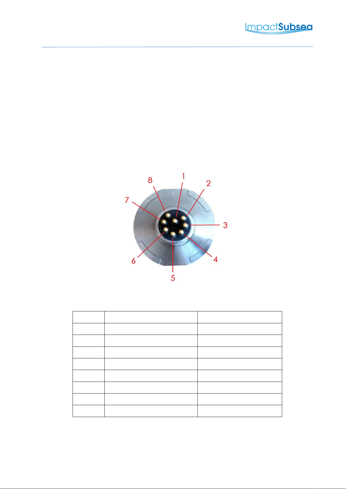
4.2.1 Connector Pin Out
The standard ISA500 connector pin out is provided below:
Male Connector on ISA500 Unit
Pin
Function
Mating Wire Colour
1
0VDC
Black
2
9-36VDC
White
3
Analogue Out
Red (Not used for FMD)
4
0V Analogue
Green (Not used for FMD)
5
0V Digital
Orange
6
Trigger
Blue (Not used for FMD)
7
RS232 TX & RS485 A+
White/Black
8
RS232 RX & RS485 B-
Red/Black
Table of contents
Other Impact Subsea Measuring Instrument manuals


